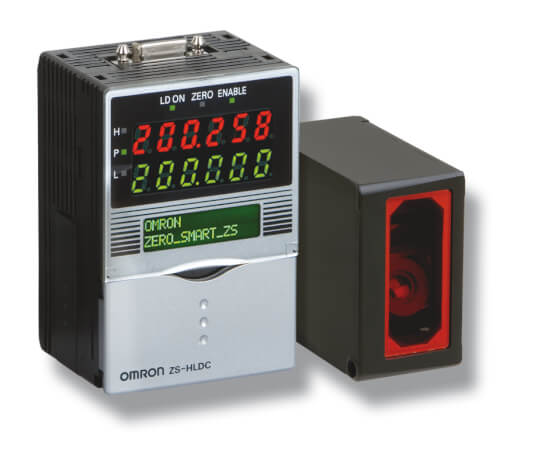
ZS-HL
Sensor láser alta precisión y escalable
El sensor inteligente ZS-HL ofrece un excelente rango de detección dinámica para todas las superficies, desde goma negra hasta superficies de cristal y reflectantes con sólo ampliarlo según las necesidades. El ZS-HL el la variante mejorada del ZS-L, y es aplicable para distancias de medida más largas, ofreciendo compatibilidad con cabezas sensoras y accesorios.
- Máxima resolución y rango de detección dinámico para todas las superficies
- Concepto de plataforma modular y ampliable hasta 9 sensores
- Fácil de utilizar, instalar y mantener para todos los niveles de usuarios
- Rápido tiempo de respuesta de 110 µs
- Capacidad multitarea, gestiona hasta 4 herramientas de medida en un solo controlador
Especificaciones y modelos disponibles
Ordering information
Sensors
ZS-HL-series sensor heads
|
Resolution1 |
|||||
|---|---|---|---|---|---|
ZS-HL-series sensor heads (for nozzle gaps) also compatible with ZS-L controller
|
Resolution2 |
|||||
|---|---|---|---|---|---|
ZS-L-series sensor heads
|
Resolution3 |
|||||
|---|---|---|---|---|---|
ZS-HL-series sensor controllers
Multi-controllers
Data storage units
Accessories (sold separately)
Controller link
Panel mount adapter
Cables for connecting to a Personal Computer
Extension cables for sensor heads
|
ZS-XC10B1 |
Logging software
Memory card
Safety precautions for using laser equipment

Specifications
Sensor heads
ZS-HL-series sensor heads
|
Visible semiconductor laser (wavelength: 650 nm, 1 mW max., JIS Clas |
Visible semiconductor laser (wavelength 658 nm, 1 mW max., Class 2) |
|||||||||
|
Beam diameter1 |
||||||||||
|
Linearity2 |
||||||||||
|
Resolution3 |
||||||||||
|
Temperature characteristic4 |
||||||||||
|
110 µs (high-speed mode), 500 µs (standard mode), 2.2 ms (high-precision mode), 4.4 ms (high-sensitivity mode) |
||||||||||
|
Lits near the measurement center, and nearer than the measurement center distance inside the measuring range. |
||||||||||
|
Lits near the measurement center, and further than the measurement center distance inside the measuring range. |
||||||||||
|
Illumination on received light surface 3,000 lx or less (incandescent light) |
Illumination on received light surface 1,000 lx or less (incandescent light) |
Illumination on received light surface 500 lx or less (incandescent light) |
||||||||
|
Operating: 0 to 50°C, storage: -15 to 60°C (with no icing or condensation) |
||||||||||
|
10 to 150 Hz, 0.7 mm double amplitude, 80 min each in X, Y, and Z directions |
||||||||||
|
150 m/s² 3 times each in six directions (up/down, left/right, forward/backward) |
||||||||||
*1 Defined as 1/e² (13.5%) of the center optical intensity in the measurement center distance. The beam diameter is sometimes influenced by the ambient conditions of the workpiece such as leaked light from the main beam.
*2 This is the error on the measured value with respect to an ideal straight line. Linear curve may change according to the workpiece. The following lists the workpieces
*3 This is the “peak-to-peak” displacement conversion value of the displacement output in the measurement center distance when high-resolution mode and the average number in the table are set (For ZS-HLDS60, the maximum resolution at 250 mm is also included). The following lists the workpieces.
*4 Value obtained when the sensor part and object part are fixed with an aluminum jig.
ZS-L-series sensor heads
|
Visible semiconductor laser (wavelength: 650 nm, 1 mW max., JIS Class 2) |
|||||||||
|
Beam diameter6 |
|||||||||
|
Linearity7 |
|||||||||
|
Resolution8 |
|||||||||
|
Temperature characteristic9 |
|||||||||
|
Sampling cycle10 |
110 µs (high-speed mode), 500 µs (standard mode), 2.2 ms (high-precision mode), 4.4 ms (high-sensitivity mode) |
||||||||
|
Lights near the measuring center distance, and nearer than the measuring center distance inside the measuring range. Flashes when the measurement target is outside of the measuring range or when the received light amount is insufficient. |
|||||||||
|
Lights near the measuring center distance, and further than the measuring center distance inside the measuring range. Flashes when the measurement target is outside of the measuring range or when the received light amount is insufficient. |
|||||||||
|
Illumination on received light surface: 3,000 lx or less (incandescent light) |
|||||||||
|
Operating: 0 to 50°C, storage: -15 to 60°C (with no icing or condensation) |
|||||||||
|
Laser labels (1 each for JIS/EN, 3 for FDA), ferrite cores (2), insure Locks (2), instruction sheet |
Laser safety labels (1 each for JIS/EN),ferrite cores (2), insure locks (2) |
||||||||
ZS-L-series sensor heads
|
Visible semiconductor laser (wavelength: 650 nm, 1 mW max., JIS Class 2) |
||||||||||||
|
Beam diameter11 |
||||||||||||
|
Linearity12 |
||||||||||||
|
Resolution13 |
||||||||||||
|
Temperature characteristic14 |
||||||||||||
|
Sampling cycle15 |
110 µs (high-speed mode), 500 µs (standard mode), 2.2 ms (high-precision mode), 4.4 ms (high-sensitivity mode) |
|||||||||||
|
Lights near the measuring center distance, and nearer than the measuring center distance inside the measuring range. Flashes when the measurement target is outside of the measuring range or when the received light amount is insufficient. |
||||||||||||
|
Lights near the measuring center distance, and further than the measuring center distance inside the measuring range. Flashes when the measurement target is outside of the measuring range or when the received light amount is insufficient. |
||||||||||||
|
Illumination on received light surface: 3,000 lx or less (incandescent light) |
Illumination on received light surface: 2,000 lx or less (incandescent light) |
Illumination on received light surface: 3,000 lx or less (incandescent light) |
||||||||||
|
Operating: 0 to 50°C, storage: -15 to 60°C (with no icing or condensation) |
||||||||||||
|
Laser labels (1 each for JIS/EN, 3 for FDA), ferrite cores (2), insure Locks (2), instruction sheet |
||||||||||||
Sensor controllers
ZS-HL-series sensor controllers
ZS-MDC11/MDC41 multi controllers
Basic specifications are the same as those for the sensor controllers.
The following points, however, are different.
(1) Sensor heads cannot be connected.
(2) A maximum 9 of controllers can be connected. Control link units are required to connect controllers.
(3) Processing functions between controllers: Math functions
Controller link unit

Data storage units
|
10 controllers max. (ZS-MDC: 1 controller, ZS-HLDC: 9 controllers max.)16 |
||||
|
Serial I/O: connector, other: pre-wired (standard cable length: 2 m) |
||||
|
3 outputs: HIGH, PASS, and LOW
NPN open-collector, 30 VDC, 50 mA max., |
3 outputs: HIGH, PASS, and LOW
PNP open-collector, 50 mA max., |
|||
|
ON: Short-circuited to supply voltage or within 1.5 V of supply voltage |
||||
|
Start and stop triggers can be set separately; external triggers, data triggers (self-triggers), and time triggers |
||||
|
External banks, alarm outputs, saved data format customization, and clock |
||||
|
16 digitsx2 rows, color of characters: green, resolution per character: 5x8 pixel matrix |
||||
|
Direction keys (UP, DOWN, LEFT, and RIGHT), SET key, ESC key, MENU key, and function keys (1 to 4) |
||||
|
Threshold switch (2 states: High/Low), mode switch (3 states: FUN, TEACH, and RUN) |
||||
|
Operating: 0 to 50°C, storage: -15 to 60°C (with no icing or condensation) |
||||
|
Ferrite core (1) instruction sheet, tools for data storage unit: CSV file converter for data storage unit, smart analyzer macro edition |
||||
3. This is the peak-to-peak displacement conversion value in the displacement output at the measuring center distance in high-precision mode when the number of samples to average is set to 128 and the measuring mode is set to the high-resolution mode. The standard workpiece is white aluminum ceramics in diffuse reflection mode and glass in the regular reflection mode.
6. Defined as 1/e² (13.5%) of the center optical intensity at the actual measurement center distance (effective value). The beam diameter is sometimes influenced by the ambient conditions of the workpiece, such as leaked light from the main beam.
7. This is the error in the measured value with respect to an ideal straight line. The standard workpiece is white aluminum ceramics in diffuse reflection mode and glass in the regular reflection mode of the ZS-LD20T/40T/50. Linearity may change according to the workpiece.
8. This is the peak-to-peak displacement conversion value in the displacement output at the measuring center distance in high-precision mode when the number of samples to average is set to 128 and the measuring mode is set to the high-resolution mode. The standard workpiece is white aluminum ceramics in diffuse reflection mode and glass in the regular reflection mode.
9. This is the value obtained at the measuring center distance when the Sensor and workpiece are fixed by an aluminum jig.
11. Defined as 1/e² (13.5%) of the center optical intensity at the actual measurement center distance (effective value). The beam diameter is sometimes influenced by the ambient conditions of the workpiece, such as leaked light from the main beam.
12. This is the error in the measured value with respect to an ideal straight line. The standard workpiece is white aluminum ceramics in diffuse reflection mode and glass in the regular reflection mode of the ZS-LD20T/40T/50. Linearity may change according to the workpiece.
13. This is the peak-to-peak displacement conversion value in the displacement output at the measuring center distance in high-precision mode when the number of samples to average is set to 128 and the measuring mode is set to the high-resolution mode. The standard workpiece is white aluminum ceramics in diffuse reflection mode and glass in the regular reflection mode.
*1 Defined as 1/e² (13.5%) of the center optical intensity in the measurement center distance. The beam diameter is sometimes influenced by the ambient conditions of the workpiece such as leaked light from the main beam.
*2 This is the error on the measured value with respect to an ideal straight line. Linear curve may change according to the workpiece. The following lists the workpieces
*3 This is the “peak-to-peak” displacement conversion value of the displacement output in the measurement center distance when high-resolution mode and the average number in the table are set (For ZS-HLDS60, the maximum resolution at 250 mm is also included). The following lists the workpieces.
3. This is the peak-to-peak displacement conversion value in the displacement output at the measuring center distance in high-precision mode when the number of samples to average is set to 128 and the measuring mode is set to the high-resolution mode. The standard workpiece is white aluminum ceramics in diffuse reflection mode and glass in the regular reflection mode.
6. Defined as 1/e² (13.5%) of the center optical intensity at the actual measurement center distance (effective value). The beam diameter is sometimes influenced by the ambient conditions of the workpiece, such as leaked light from the main beam.
7. This is the error in the measured value with respect to an ideal straight line. The standard workpiece is white aluminum ceramics in diffuse reflection mode and glass in the regular reflection mode of the ZS-LD20T/40T/50. Linearity may change according to the workpiece.
8. This is the peak-to-peak displacement conversion value in the displacement output at the measuring center distance in high-precision mode when the number of samples to average is set to 128 and the measuring mode is set to the high-resolution mode. The standard workpiece is white aluminum ceramics in diffuse reflection mode and glass in the regular reflection mode.
9. This is the value obtained at the measuring center distance when the Sensor and workpiece are fixed by an aluminum jig.
11. Defined as 1/e² (13.5%) of the center optical intensity at the actual measurement center distance (effective value). The beam diameter is sometimes influenced by the ambient conditions of the workpiece, such as leaked light from the main beam.
12. This is the error in the measured value with respect to an ideal straight line. The standard workpiece is white aluminum ceramics in diffuse reflection mode and glass in the regular reflection mode of the ZS-LD20T/40T/50. Linearity may change according to the workpiece.
13. This is the peak-to-peak displacement conversion value in the displacement output at the measuring center distance in high-precision mode when the number of samples to average is set to 128 and the measuring mode is set to the high-resolution mode. The standard workpiece is white aluminum ceramics in diffuse reflection mode and glass in the regular reflection mode.
¿Necesita ayuda?
Estamos aquí para ayudarle. Póngase en contacto con nosotros y nuestros especialistas le ayudarán a encontrar la mejor solución para su negocio.
Contacten conmigo ZS-HL
Gracias por enviarnos su solicitud. Le responderemos lo antes posible.
Tenemos dificultades técnicas. Su formulario no ha sido enviado. Porfavor, acepte nuestras disculpas e inténtelo de nuevo más tarde.\ Detalle: [details]
DownloadPresupuesto para ZS-HL
A través de este formulario puede solicitar cotización del producto escogido. Por favor, cumplimente todos los campos marcados con *. Sus datos personales serán tratados con la máxima confidencialidad.

Gracias por la cotización solicitada. Le enviaremos la información solicitada lo antes posible.
Tenemos dificultades técnicas. Su formulario no ha sido enviado. Porfavor, acepte nuestras disculpas e inténtelo de nuevo más tarde.\ Detalle: [details]
DownloadCaracterísticas
Medida de la distancia de la superficie de un disco
Este sensor puede medir la inclinación de objetos con superficies muy reflectantes, como por ejemplo un disco, tomando medidas precisas de las distancias.
Grosor de la luna de un parabrisas
El sensor ZS es capaz de medir el grosor de cualquier objeto transparente con solo un cabezal.
Altura de una tira de adhesivo
El sensor puede medir de forma precisa la altura de una tira de adhesivo semitransparente.
Grosor de un objeto oscuro de goma
Mediante dos sensores y una unidad de cálculo, el sensor ZS puede determinar el grosor de cualquier material de color negro mate y textura viscosa.
Inspección del acabado de un pistón
Gracias a la acción conjunta de varios sensores, se puede comprobar el acabado de cualquier superficie reflectante mecanizada.
