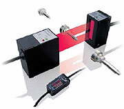
ZX-GT
Micrómetro láser inteligente - Precisión y rapidez en todas las superficies
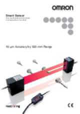
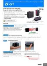
El nuevo micrómetro láser inteligente ZX-GT complementa la gama de sensores de medida inteligentes láser de Omron. El ZX-GT puede detectar bordes, medir diámetros de objetos y calcular de forma precisa la posición de todo tipo de materiales. Basado en la tecnología CCD, el ZX-GT ofrece una gran precisión y velocidad en condiciones medioambientales adversas. Los objetos transparentes, las superficies reflectantes ni las distintas posiciones afectan al resultado. El software para PC Smart Monitor facilita la instalación y configuración del micrómetro de láser.
- Gran precisión: 5 – 10µm
- Todas las superficies
- Gran distancia de detección: < 500 mm
- Ancho de medida de hasta 28 mm
- Unidad de cálculo para varias cabezas
Especificaciones y modelos disponibles
Ordering information
Sensors
Controller
Accessories (order separately)
Set of interface unit and setup software PCs
Interface unit(RS-232C/binary output)
Setup software PCs
Calculating units
Receiver-controller extension cable
Specifications
Sensor
|
Visible semiconductor laser diode (wavelength 650 nm, CLASS 1 of EN60825-1/IEC60825-1, CLASS of FDA(21CFR 1040.10 and 1040.11) |
||||
|
0.5 mm dia.1 |
0.5 mm dia.1 |
|||
|
±0.1% F.S.2 |
||||
|
10 µm (number of process values to average: 16)3 |
||||
|
±0.01% F.S/C4 |
||||
|
ON: Short-circuited with 0 V or 1.5 V max. |
ON: Short-circuited with power supply voltage or |
|||
|
NPN open-collector output |
PNP open-collector output |
|||
|
1,000 lx (incandescent light)5 |
||||
|
Operating: 0 to 40°C, storage: -15 to 50°C (with no icing or condensation) |
||||
|
10 to 150 Hz single-amplitude: 0.75 mm for 80 min each in X, Y and Z directions |
||||
Controller
|
Measurement cycle6 |
1.5 ms (standard mode (NORM)) |
||
|
Analog output8 |
For current output: 4 to 20 mA/F.S., max. load resistance 300
Ω
|
||
|
Timing input, bank switching input, zero reset input, reset input |
ON: short-circuited with 0 V or 1.5 V max. |
ON: short-circuited with power supply voltage or |
|
|
NPN open-collector output |
PNP open-collector output |
||
|
Judgment output indicator: HIGH (orange), PASS (green), LOW (orange) |
|||
|
Interrupted beam width measurement, incident beam width measurement, outer diameter measurement, center position measurement, IC lead pitch, |
|||
|
Measured value, resolution, threshold, voltage output value, current output value (number of display digits can be changed) |
|||
|
Sample hold, peak hold, bottom hold, peak-to-peak hold, average hold, delay hold |
|||
|
Optical axis adjust mode/light intensityt writing mode, variable binary level, variable edge filter, analog output scaling |
|||
|
2 possible on up to two controllers (calculation Unit ZX-CAL2 is required for connecting controllers to each other.) A-B, A+B, width |
|||
|
Measurement cycle setting, threshold setting, hysteresis setting, initialization, key lock |
|||
|
Operating: 0 to 50°C, storage: -15 to 60°C (with no icing or condensation) |
|||
|
10 to 150 Hz single-amplitude: 0.35 mm for 80 min each in X, Y and Z directions |
|||
|
Case: PBT (polybutylene terephthalate), cover: Polycarbonate |
|||
Interface unit
1. Distance between emitter and receiver: 500 mm, measurement object at 250 mm from receiver. Glass ends of chamfer 0.1 mm or more can be detected in glass edge measurement mode. (at binary level 70%)
2. Linearity is given to be a typical error with respect to an ideal straight line when the distance between the emitter and receiver is 100 mm and light is blocked at a distance of 50 mm from the receiver. (On the ZX-GT2840_, the measurement object is measured at a distance of 20 mm from the receiver.)
3. The amount of fluctuation (±3 σ ) in the analog output when the distance between the emitter and receiver is 100 mm and a ZX-GTC_ is connected
4.
Change in the light cutoff value on one side when the distance between the emitter and receiver is 100 mm and the light is half-cutoff at a distance of 50 mm from the receiver (On the
ZX-GT2840_, the measurement object is measured at a distance of 20 mm from the receiver.)
6. The first response time is “measurement cycle x (number of samples to average setting + 1) + 1 ms” max. For the second response time onwards, the specified measurement cycle time is output.
7. The response time in the high-speed mode (FAST) for the IC lead pitch and IC lead width judgment modes is 1 ms.
11.
Normally, wire the sync output wire directly to the emitter's sync input wire and run the controller in the standard mode. On an NPN type controller, use an NPN type emitter, and on a PNP type controller, use a PNP type emitter. Wiring of the sync wires is not required when the controller is run in the high-speed mode.
(Note, however, that the controller becomes more susceptible to the influence of ambient light in this case.)
¿Necesita ayuda?
Estamos aquí para ayudarle. Póngase en contacto con nosotros y nuestros especialistas le ayudarán a encontrar la mejor solución para su negocio.
Contacten conmigo ZX-GT
Gracias por enviarnos su solicitud. Le responderemos lo antes posible.
Tenemos dificultades técnicas. Su formulario no ha sido enviado. Porfavor, acepte nuestras disculpas e inténtelo de nuevo más tarde.\ Detalle: [details]
Presupuesto para ZX-GT
A través de este formulario puede solicitar cotización del producto escogido. Por favor, cumplimente todos los campos marcados con *. Sus datos personales serán tratados con la máxima confidencialidad.
Gracias por la cotización solicitada. Le enviaremos la información solicitada lo antes posible.
Tenemos dificultades técnicas. Su formulario no ha sido enviado. Porfavor, acepte nuestras disculpas e inténtelo de nuevo más tarde.\ Detalle: [details]
Descargas
_41(a)_instruction_sheet_en.jpg)