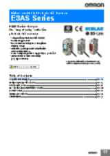
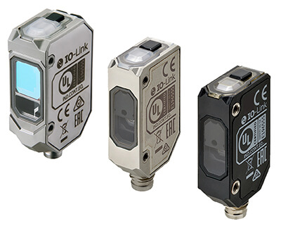
E3AS
Sensores fotoeléctricos de reflexión directa avanzados
La serie E3AS cambia la "forma de utilizar" sensores fotoeléctricos
- Amplia gama de soluciones de hasta 1,5 m.
- Detección de alta fiabilidad de objetos brillantes, irregulares y transparentes.
- Haz de punto y haz de línea para objetos difíciles de detectar.
- Detección de objetos transparentes sin espejo.
- Pantalla OLED para facilitar la navegación y los ajustes avanzados.
- El tamaño reducido del cuerpo permite su instalación en cualquier lugar.
- Fabricado con el método de sellado por láser patentado de OMRON.
- IP67/IP69K/IP67G.
- Los revestimientos antiincrustantes reducen la frecuencia con la que se debe limpiar la superficie de detección.
- El sistema IO-Link reduce el tiempo necesario para la puesta en marcha y los cambios.
- Accesorio de soplado para un mantenimiento sencillo.
- Equipado con el elemento emisor de luz patentado de OMRON para una detección estable de piezas poco reflectantes.
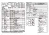
Especificaciones y modelos disponibles
| Producto | Shape | Sensing method | Sensing distance | Sensing distance (min.) | Setting method | Connection method | Cable length | Output type | Operation mode | Response time | Material housing | Type of light | Laser class | Spot size | Power supply voltage | Functions | Features | Degree of protection (IP) | Descripción | |
|---|---|---|---|---|---|---|---|---|---|---|---|---|---|---|---|---|---|---|---|---|
|
|
Cuboid | Background suppression | 1000 mm | 50 mm | Teach-In | Cable | 2 m | NPN | Dark-ON, Light-ON | 90 ms | Stainless steel | Laser diode, infrared light | 1 | 95 mm | 10-30 V | TOF (Time of Flight) | Photoelectric sensor, rectangular housing, stainless steel, infrared laser class 1, time-of-flight, 1000 mm, NPN, Light-ON/Dark-ON, 2 m cable |
|
||
|
|
Cuboid | Background suppression | 1000 mm | 50 mm | Teach-In | Connector M8 - 4 pin | NPN | Dark-ON, Light-ON | 90 ms | Stainless steel | Laser diode, infrared light | 1 | 95 mm | 10-30 V | TOF (Time of Flight) | Photoelectric sensor, rectangular housing, stainless steel, infrared laser class 1, time-of-flight, 1000 mm, NPN, Light-ON/Dark-ON, M8 4-pin connector |
|
|||
|
|
Cuboid | Background suppression | 1000 mm | 50 mm | Teach-In | M12 pigtail Smartclick connector | 0.3 m | NPN | Dark-ON, Light-ON | 90 ms | Stainless steel | Laser diode, infrared light | 1 | 95 mm | 10-30 V | TOF (Time of Flight) | Photoelectric sensor, rectangular housing, stainless steel, infrared laser class 1, time-of-flight, 1000 mm, NPN, Light-ON/Dark-ON, M12 pigtail Smartclick connector, 0.3 m |
|
||
|
|
Cuboid | Background suppression | 1000 mm | 50 mm | IO-Link, Teach-In | Cable | 2 m | IO-Link, PNP | Dark-ON, Light-ON | 90 ms | Stainless steel | Laser diode, infrared light | 1 | 95 mm | 10-30 V | TOF (Time of Flight) | Fotocélula, compacta cuadrada, acero inoxidable, TOF, 1000 mm, láser infrarrojo, PNP, L-ON/D-ON, IO-Link COM3, precableado de 2 m |
|
||
|
|
Cuboid | Background suppression | 1000 mm | 50 mm | IO-Link, Teach-In | Connector M8 - 4 pin | IO-Link, PNP | Dark-ON, Light-ON | 90 ms | Stainless steel | Laser diode, infrared light | 1 | 95 mm | 10-30 V | TOF (Time of Flight) | Fotocélula, compacta cuadrada, acero inoxidable, TOF, 1000 mm, láser infrarrojo, PNP, L-ON/D-ON, IO-Link COM3, conector M8 de 4 contactos |
|
|||
|
|
Cuboid | Background suppression | 1000 mm | 50 mm | IO-Link, Teach-In | M12 pigtail Smartclick connector | 0.3 m | IO-Link, PNP | Dark-ON, Light-ON | 90 ms | Stainless steel | Laser diode, infrared light | 1 | 95 mm | 10-30 V | TOF (Time of Flight) | Photoelectric sensor, rectangular housing, stainless steel, infrared laser class 1, time-of-flight, 1000 mm, PNP, Light-ON/Dark-ON, IO-Link COM3, M12 pigtail Smartclick connector, 0.3 m |
|
||
|
|
Cuboid | Background suppression | 1000 mm | 50 mm | Teach-In | Cable | 2 m | NPN | Dark-ON, Light-ON | 90 ms | PBT | Laser diode, infrared light | 1 | 95 mm | 10-30 V | TOF (Time of Flight) | Photoelectric sensor, rectangular housing, plastic body, infrared laser class 1, time-of-flight, 1000 mm, NPN, Light-ON/Dark-ON, 2 m cable |
|
||
|
|
Cuboid | Background suppression | 1000 mm | 50 mm | Teach-In | Connector M8 - 4 pin | NPN | Dark-ON, Light-ON | 90 ms | PBT | Laser diode, infrared light | 1 | 95 mm | 10-30 V | TOF (Time of Flight) | Photoelectric sensor, rectangular housing, plastic body, infrared laser class 1, time-of-flight, 1000 mm, NPN, Light-ON/Dark-ON, M8 4-pin connector |
|
|||
|
|
Cuboid | Background suppression | 1000 mm | 50 mm | Teach-In | M12 pigtail Smartclick connector | 0.3 m | NPN | Dark-ON, Light-ON | 90 ms | PBT | Laser diode, infrared light | 1 | 95 mm | 10-30 V | TOF (Time of Flight) | Photoelectric sensor, rectangular housing, plastic body, infrared laser class 1, time-of-flight, 1000 mm, NPN, Light-ON/Dark-ON, M12 pigtail Smartclick connector, 0.3 m |
|
||
|
|
Cuboid | Background suppression | 1000 mm | 50 mm | IO-Link, Teach-In | Cable | 2 m | IO-Link, PNP | Dark-ON, Light-ON | 90 ms | PBT | Laser diode, infrared light | 1 | 95 mm | 10-30 V | TOF (Time of Flight) | IP67/IP67G/IP69K | Photoelectric sensor, rectangular housing, plastic body, infrared laser class 1, time-of-flight, 1000 mm, PNP, Light-ON/Dark-ON, IO-Link COM3, 2 m cable |
|
|
|
|
Cuboid | Background suppression | 1000 mm | 50 mm | IO-Link, Teach-In | Cable | 5 m | IO-Link, PNP | Dark-ON, Light-ON | 90 ms | PBT | Laser diode, infrared light | 1 | 95 mm | 10-30 V | TOF (Time of Flight) | IP67/IP67G/IP69K | Photoelectric sensor, rectangular housing, plastic body, infrared laser class 1, time-of-flight, 1000 mm, PNP, Light-ON/Dark-ON, IO-Link COM3, 5 m cable |
|
|
|
|
Cuboid | Background suppression | 1000 mm | 50 mm | IO-Link, Teach-In | Connector M8 - 4 pin | IO-Link, PNP | Dark-ON, Light-ON | 90 ms | PBT | Laser diode, infrared light | 1 | 95 mm | 10-30 V | TOF (Time of Flight) | IP67/IP67G/IP69K | Fotocélula, compacta cuadrada, cuerpo de plástico, TOF, 1000 mm, láser infrarrojo, PNP, L-ON/D-ON, IO-Link COM3, conector M8 de 4 contactos |
|
||
|
|
Cuboid | Background suppression | 1000 mm | 50 mm | IO-Link, Teach-In | M12 pigtail Smartclick connector | 0.3 m | IO-Link, PNP | Dark-ON, Light-ON | 90 ms | PBT | Laser diode, infrared light | 1 | 95 mm | 10-30 V | TOF (Time of Flight) | IP67/IP67G/IP69K | Photoelectric sensor, rectangular housing, plastic body, infrared laser class 1, time-of-flight, 1000 mm, PNP, Light-ON/Dark-ON, IO-Link COM3, M12 pigtail Smartclick connector, 0.3 m |
|
|
|
|
Cuboid | Background suppression | 1000 mm | 50 mm | IO-Link, Teach-In | M8 pigtail connector 4 pin | 0.3 m | IO-Link, PNP | Dark-ON, Light-ON | 90 ms | PBT | Laser diode, infrared light | 1 | 95 mm | 10-30 V | TOF (Time of Flight) | IP67/IP67G/IP69K | Photoelectric sensor, rectangular housing, plastic body, infrared laser class 1, time-of-flight, 1000 mm, PNP, Light-ON/Dark-ON, IO-Link COM3, M8 pigtail connector 4-pin, 0.3 m |
|
|
|
|
Cuboid | Background suppression | 1500 mm | 50 mm | Teach-In | Cable | 2 m | NPN | Dark-ON, Light-ON | 150 ms | Stainless steel | Laser diode, infrared light | 1 | 95 mm | 10-30 V | TOF (Time of Flight) | IP67/IP67G/IP69K | Photoelectric sensor, rectangular housing, stainless steel, infrared laser class 1, time-of-flight, 1500 mm, NPN, Light-ON/Dark-ON, 2 m cable |
|
|
|
|
Cuboid | Background suppression | 1500 mm | 50 mm | Teach-In | Connector M8 - 4 pin | NPN | Dark-ON, Light-ON | 150 ms | Stainless steel | Laser diode, infrared light | 1 | 95 mm | 10-30 V | TOF (Time of Flight) | Photoelectric sensor, rectangular housing, stainless steel, infrared laser class 1, time-of-flight, 1500 mm, NPN, Light-ON/Dark-ON, M8 4-pin connector |
|
|||
|
|
Cuboid | Background suppression | 1500 mm | 50 mm | Teach-In | M12 pigtail Smartclick connector | 0.3 m | NPN | Dark-ON, Light-ON | 150 ms | Stainless steel | Laser diode, infrared light | 1 | 95 mm | 10-30 V | TOF (Time of Flight) | Photoelectric sensor, rectangular housing, stainless steel, infrared laser class 1, time-of-flight, 1500 mm, NPN, Light-ON/Dark-ON, M12 pigtail Smartclick connector, 0.3 m |
|
||
|
|
Cuboid | Background suppression | 1500 mm | 50 mm | IO-Link, Teach-In | Cable | 2 m | IO-Link, PNP | Dark-ON, Light-ON | 150 ms | Stainless steel | Laser diode, infrared light | 1 | 95 mm | 10-30 V | TOF (Time of Flight) | Photoelectric sensor, rectangular housing, stainless steel, infrared laser class 1, time-of-flight, 1500 mm, PNP, Light-ON/Dark-ON, IO-Link COM3, 2 m cable |
|
||
|
|
Cuboid | Background suppression | 1500 mm | 50 mm | IO-Link, Teach-In | Connector M8 - 4 pin | IO-Link, PNP | Dark-ON, Light-ON | 150 ms | Stainless steel | Laser diode, infrared light | 1 | 95 mm | 10-30 V | TOF (Time of Flight) | Fotocélula, compacta cuadrada, acero inoxidable, TOF, 1500 mm, láser infrarrojo, PNP, L-ON/D-ON, IO-Link COM3, conector M8 de 4 contactos |
|
|||
|
|
Cuboid | Background suppression | 1500 mm | 50 mm | IO-Link, Teach-In | M12 pigtail Smartclick connector | 0.3 m | IO-Link, PNP | Dark-ON, Light-ON | 150 ms | Stainless steel | Laser diode, infrared light | 1 | 95 mm | 10-30 V | TOF (Time of Flight) | Photoelectric sensor, rectangular housing, stainless steel, infrared laser class 1, time-of-flight, 1500 mm, PNP, Light-ON/Dark-ON, IO-Link COM3, M12 pigtail Smartclick connector, 0.3 m |
|
¿Necesita ayuda?
Estamos aquí para ayudarle. Póngase en contacto con nosotros y nuestros especialistas le ayudarán a encontrar la mejor solución para su negocio.
Contacten conmigo E3AS
Gracias por enviarnos su solicitud. Le responderemos lo antes posible.
Tenemos dificultades técnicas. Su formulario no ha sido enviado. Porfavor, acepte nuestras disculpas e inténtelo de nuevo más tarde.\ Detalle: [details]
DownloadPresupuesto para E3AS
A través de este formulario puede solicitar cotización del producto escogido. Por favor, cumplimente todos los campos marcados con *. Sus datos personales serán tratados con la máxima confidencialidad.
Gracias por la cotización solicitada. Le enviaremos la información solicitada lo antes posible.
Tenemos dificultades técnicas. Su formulario no ha sido enviado. Porfavor, acepte nuestras disculpas e inténtelo de nuevo más tarde.\ Detalle: [details]
DownloadCaracterísticas
E3AS-HL para cintas transportadoras de varias líneas con superficie curva
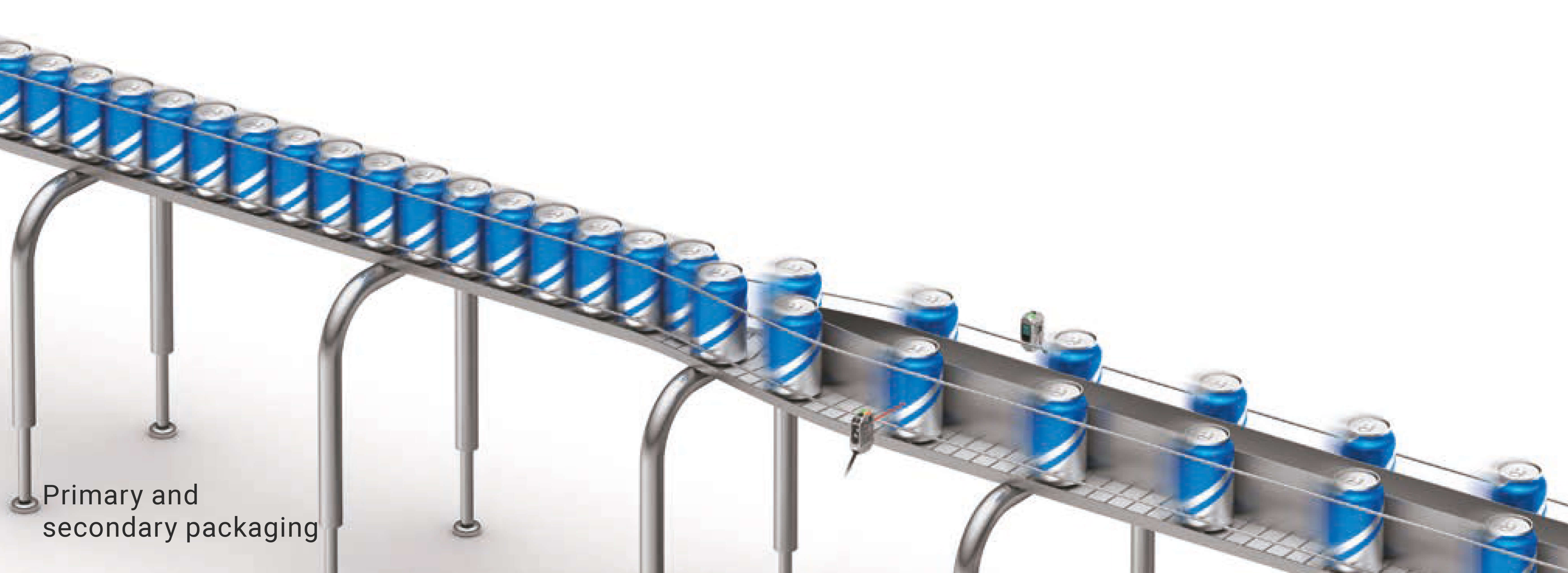
Detecta latas y botellas de plástico de manera estable y sin espejos
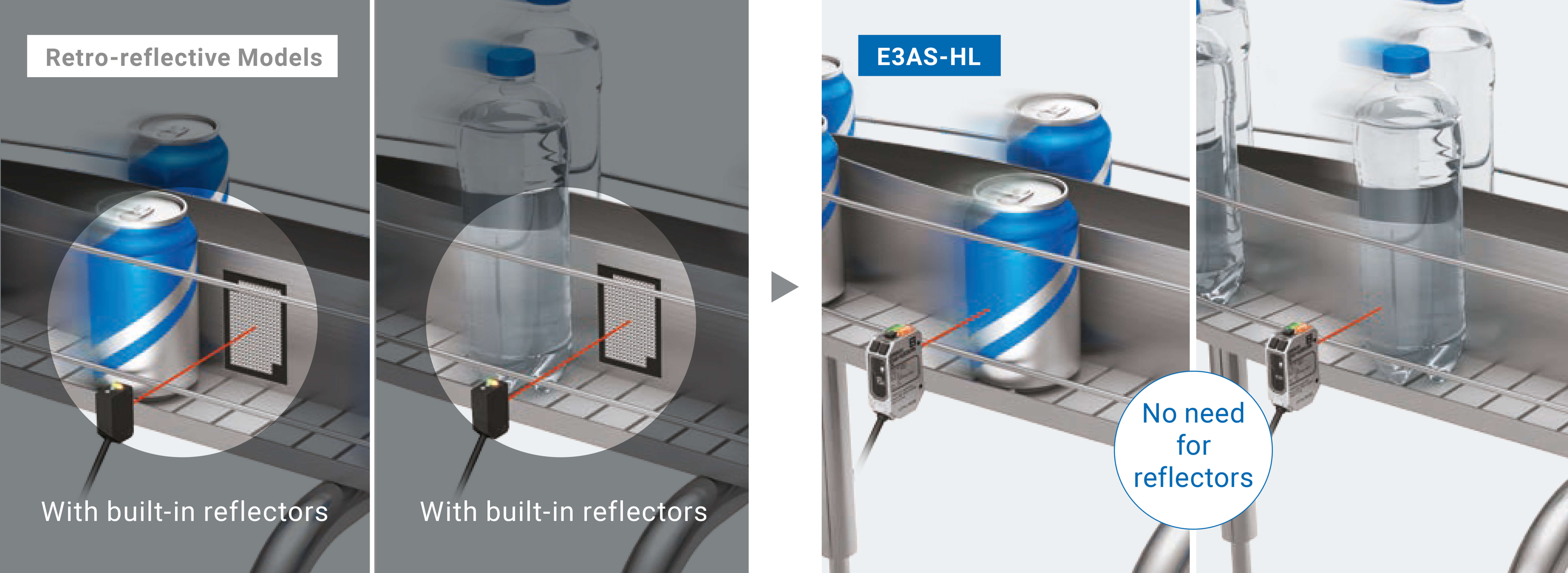
Imagen izquierda: los sensores retrorreflexivos se utilizan para detectar superficies curvas poco reflectantes de latas y botellas de plástico transparentes. Sin embargo, es complicado asegurar el espacio necesario para instalar los espejos en las cintas transportadoras de varias líneas.
Imagen derecha: el sensor E3AS-HL, un modelo reflexivo capaz de detectar el más mínimo cambio en el nivel o la distancia de la luz incidente, puede detectar de forma estable latas y botellas de plástico sin espejos.
E3AS-HL para objetivos de formas complejas, de color, con estampado o brillantes
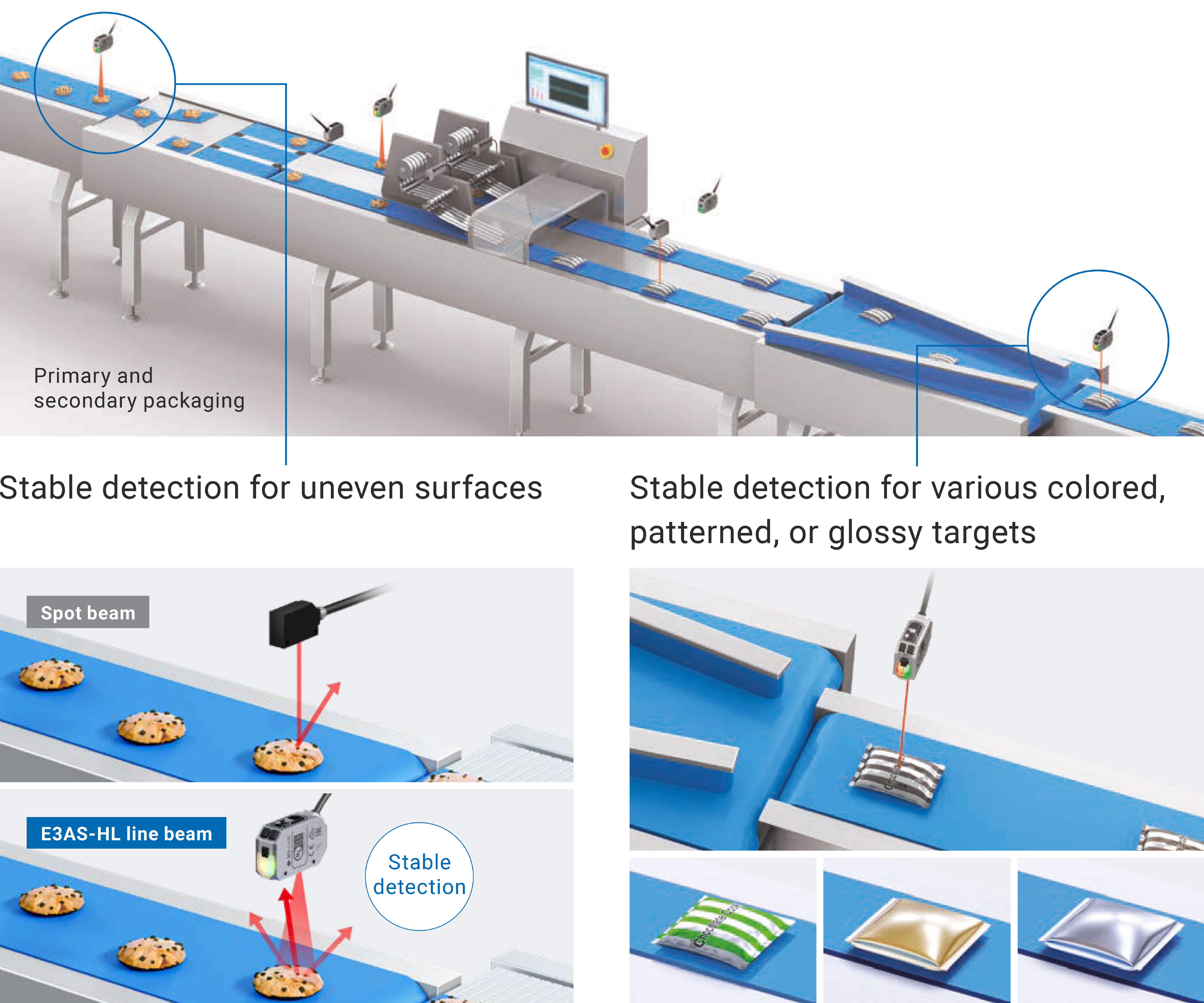
Imagen izquierda: con el haz de punto, la detección es inestable, ya que la luz reflejada depende del perfil de la superficie del objetivo para llegar al sensor. Sin embargo, gracias al haz de línea del sensor E3AS-HL, el perfil de la superficie afecta menos a la detección, ya que la luz reflejada llega al sensor desde cualquier parte de la superficie.
Imagen derecha: la detección tiende a ser inestable debido a que el color, el estampado o la reflectividad influyen en la distancia de detección. Es menos probable que estos factores afecten al sensor E3AS-HL, por lo que proporciona una detección estable incluso cuando cambian los materiales de envasado.
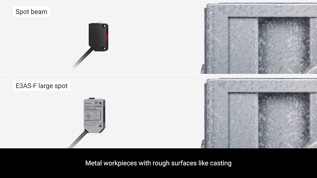
E3AS-F para detección de larga distancia en líneas convergentes y divergentes
No se requieren espejos para diseñar un sistema de detección de larga distancia que no se vea afectado por el color o el material de los objetivos
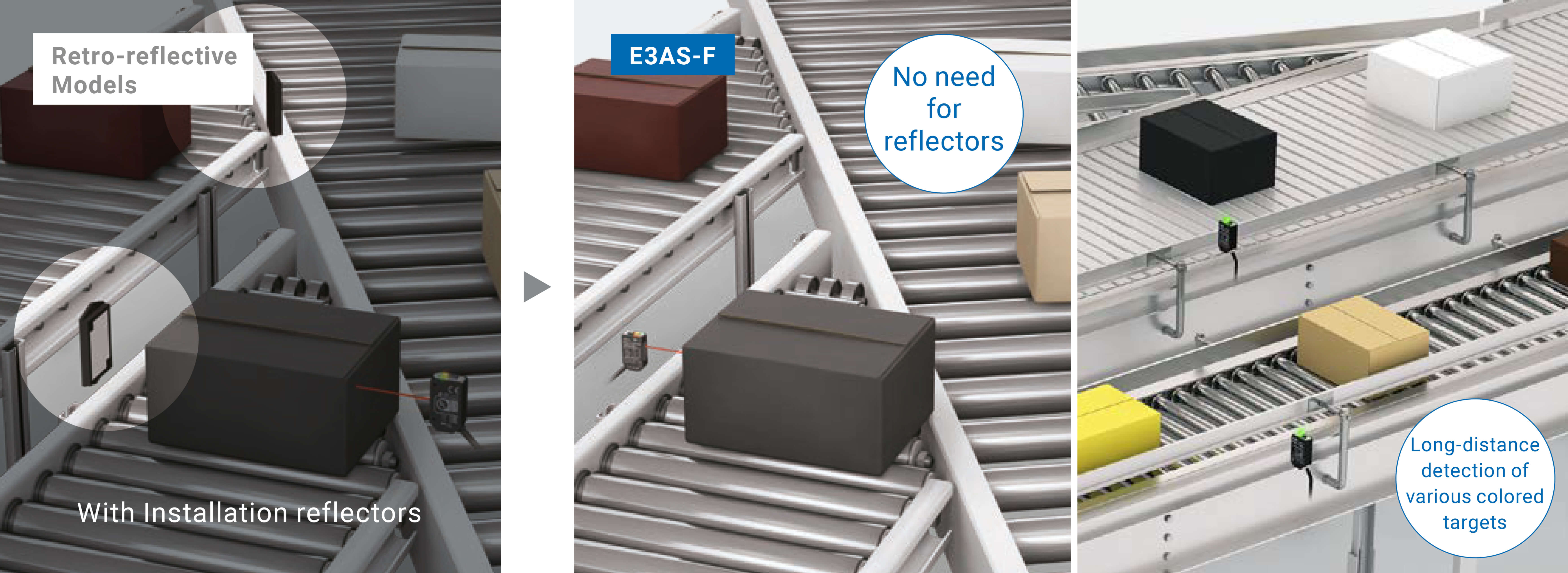
Aunque se utilicen sensores retrorreflexivos para la detección de larga distancia en líneas convergentes y divergentes, resulta complicado hallar el espacio necesario para instalar los espejos.
El sensor E3AS-HL, un modelo reflexivo de larga distancia de detección, no requiere espejos. Además, es menos probable que se vea afectado por el color, incluso en distancias largas.
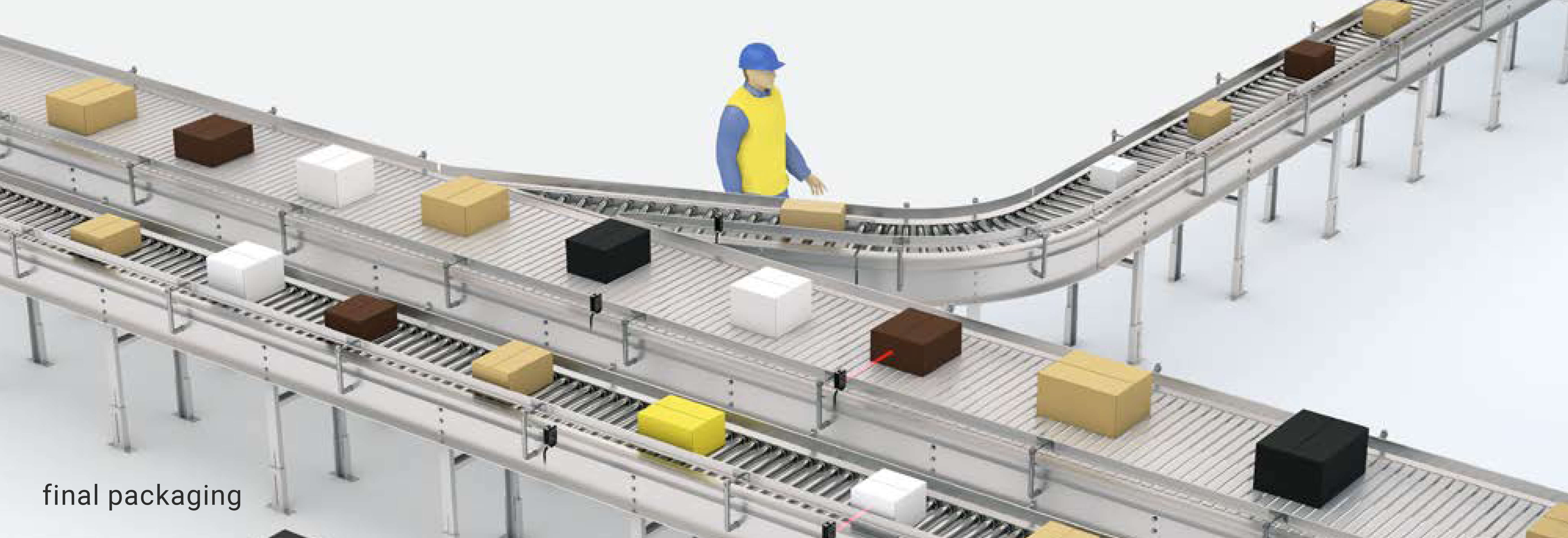
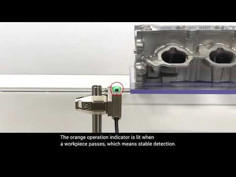
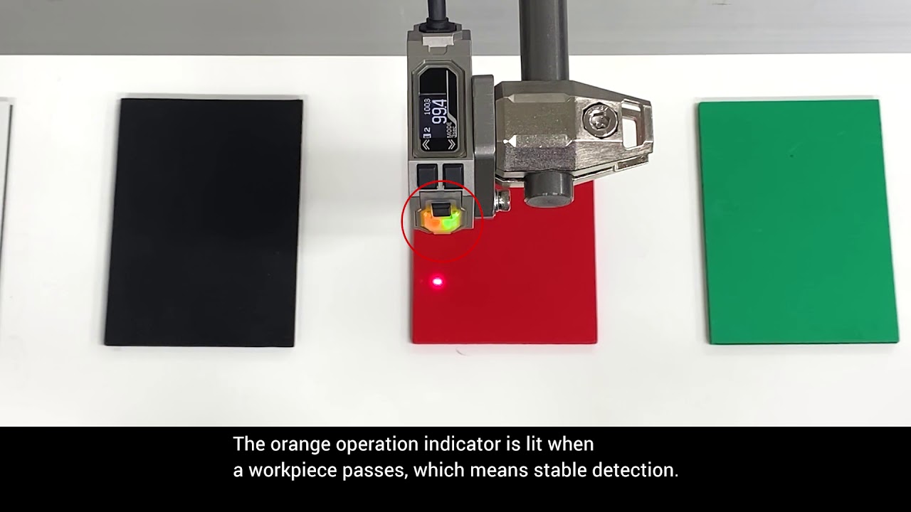
El método TOF permite la detección de varias piezas en la cinta transportadora
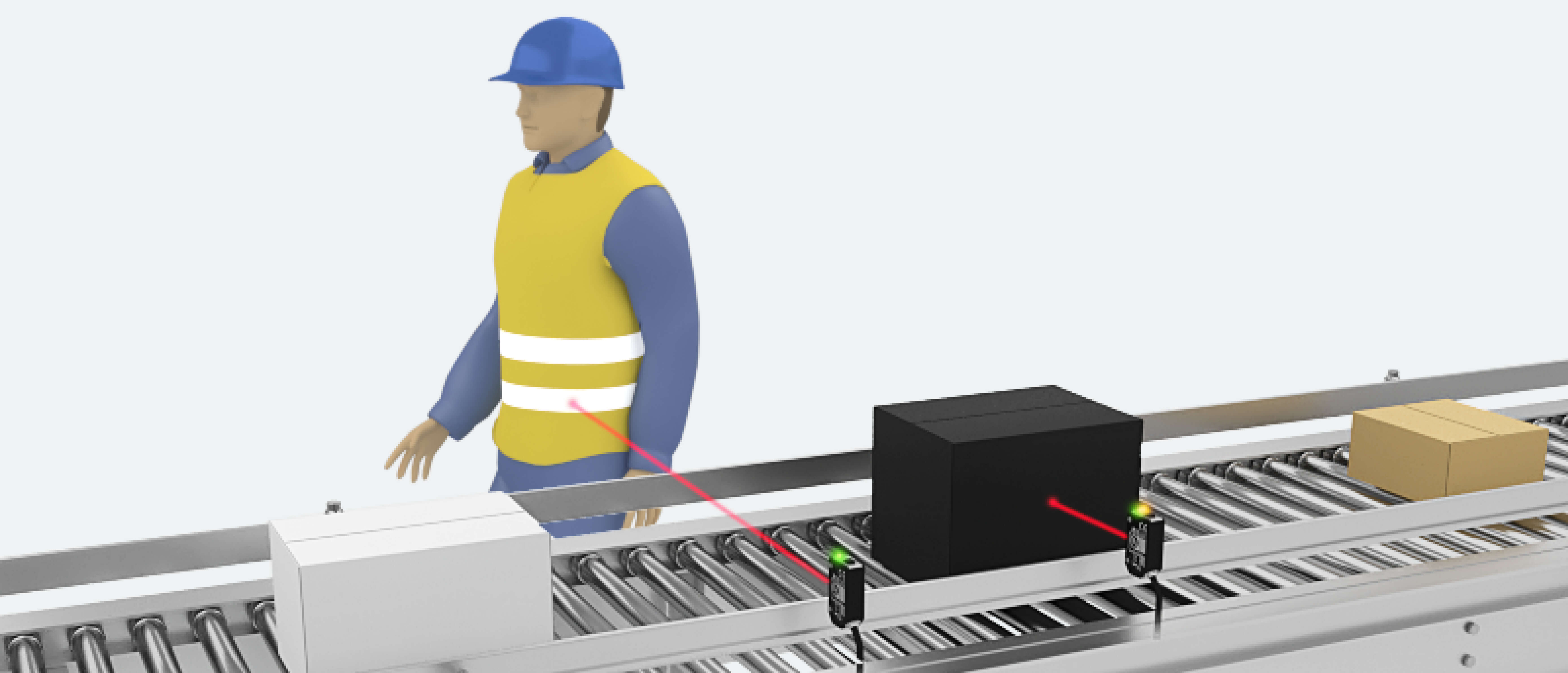
Los sensores fotoeléctricos convencionales precisaban de una evaluación previa para la detección de cada pieza. Los sensores E3AS-F detectan piezas de diversos colores y materiales en función de la distancia establecida. De esta manera, se reducen los tiempos de evaluación y ajuste. Además, estos sensores no detectan por error a los trabajadores situados cerca de la cinta.
Recubrimiento antiincrustante que evita que se ensucie la superficie de detección

Debido al principio de funcionamiento de los sensores fotoeléctricos, una superficie de detección sucia puede provocar detecciones erróneas. La serie E3AS es la primera de la industria que incorpora un revestimiento antiincrustante para evitar que se adhieran gotas de agua, aceite y polvo a la superficie de detección, además de impedir que esta se empañe. De esta forma, el revestimiento evita que se ensucie la superficie de detección en entornos con aceite y polvo o en los que se genere vapor. Además, reduce el número de falsos positivos y la frecuencia con la que debe limpiarse.
Tecnologías de soldadura láser aplicables a una variedad de materiales y metales para una mayor resistencia ambiental
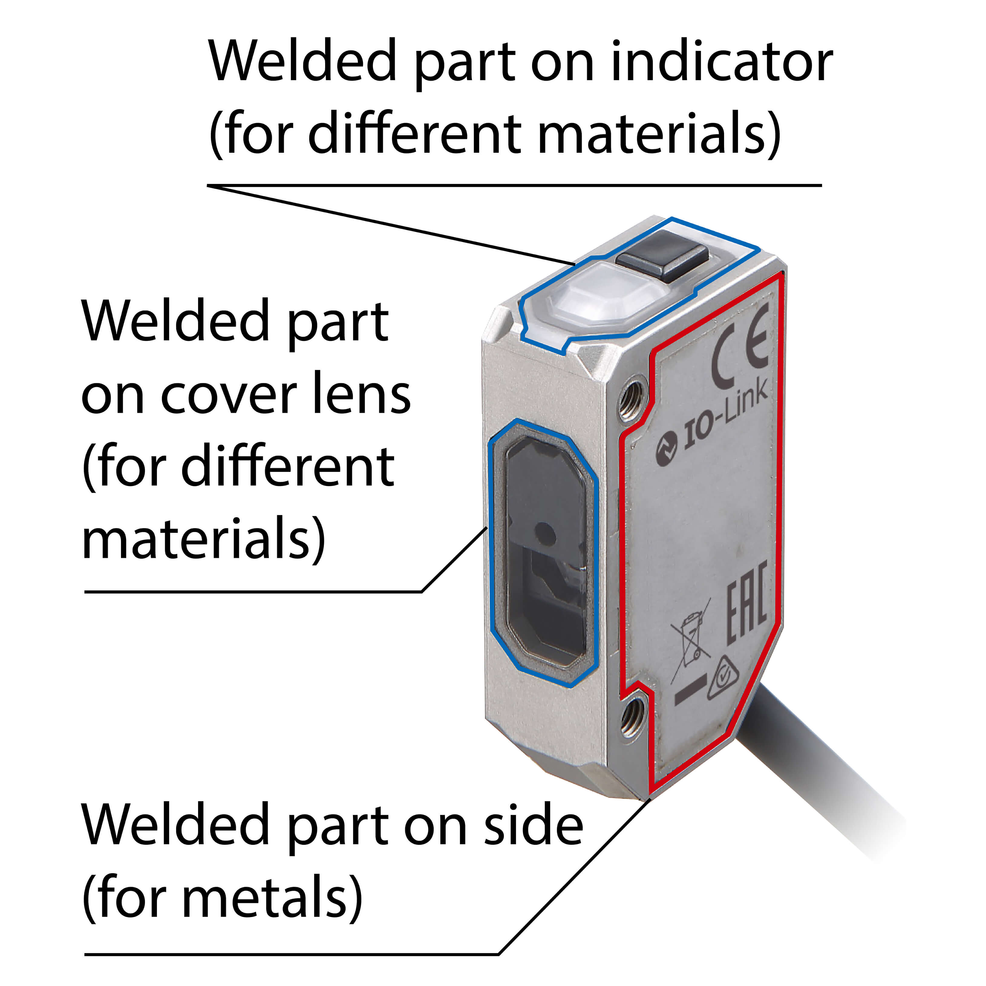
La carcasa del sensor está fabricada en acero inoxidable (SUS316L). Las dos tecnologías de soldadura láser exclusivas de OMRON, una para diversos tipos de materiales y otra para metales, han permitido mejorar el sellado y la adhesión entre el acero inoxidable y la resina.
Tecnología de soldadura láser para diferentes materiales
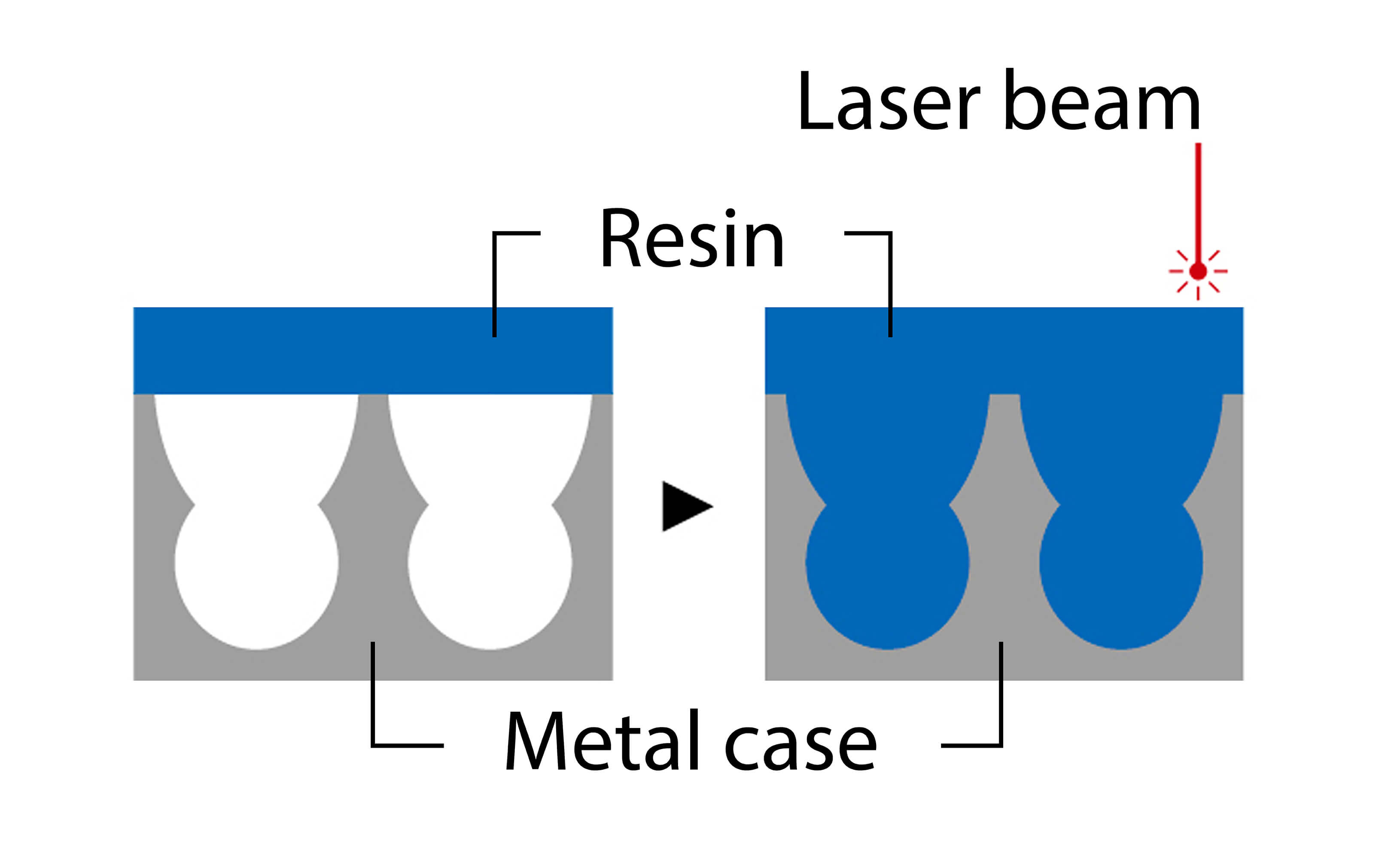
Se trata de una tecnología para soldar diferentes materiales, como resina y metal, mediante haces láser. Se perforan pequeños orificios en la carcasa metálica y, a continuación, se funde la pieza de resina mediante el láser. La resina fundida rellena los orificios, lo que garantiza una adhesión y un sellado seguros.
Tecnología de soldadura láser para metales
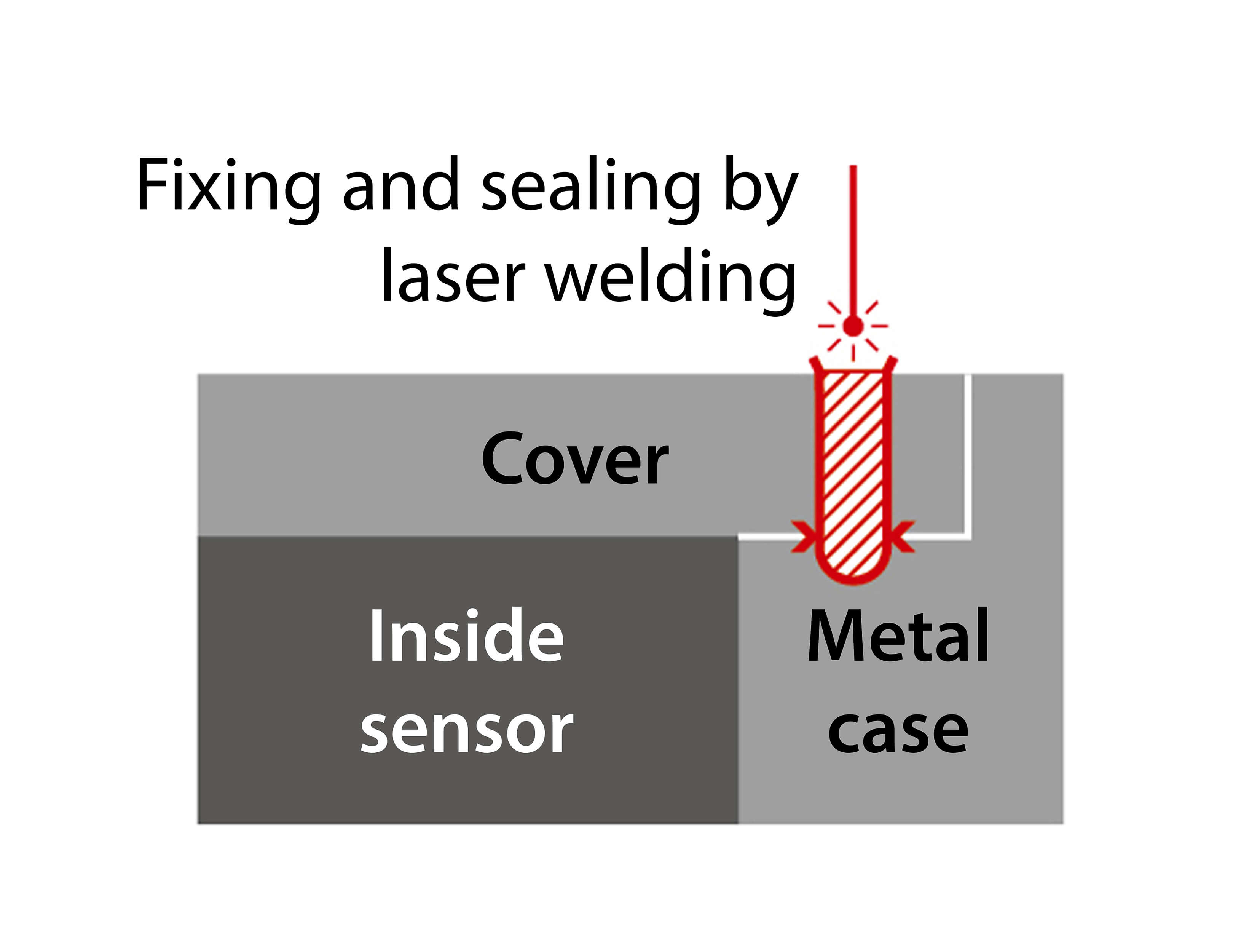
La carcasa y cubierta metálicas se sueldan mediante un haz láser para sellar los huecos. Esto proporciona una mayor hermeticidad que la adhesión, lo que evita que se filtre agua, aceite y otras sustancias, y reduce la posibilidad de que se produzcan fallos.
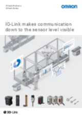
Vídeos

-

Look inside the E3AS photoelectric sensor: 3D blowout video
OMRON's E3AS advanced reflective photoelectric sensors are ideal for quick and easy equipment design and commissioning. Take a look inside for the detailed features, and read more here:
00:39
Look inside the E3AS photoelectric sensor: 3D blowout video
OMRON's E3AS advanced reflective photoelectric sensors are ideal for quick and easy equipment design and commissioning. Take a look inside for the detailed features, and read more here:

Omron E3AS Photoelectric Sensors | Easy selection for any application

-

OMRON E3AS Photoelectric Sensors | Flexible to design for Food Industry without reflectors.
E3AS-HL CMOS sensor for multi-lane conveyor lines of workpieces with curved surfaces, with sensing distance up to 500mm.
01:58
OMRON E3AS Photoelectric Sensors | Flexible to design for Food Industry without reflectors.
E3AS-HL CMOS sensor for multi-lane conveyor lines of workpieces with curved surfaces, with sensing distance up to 500mm.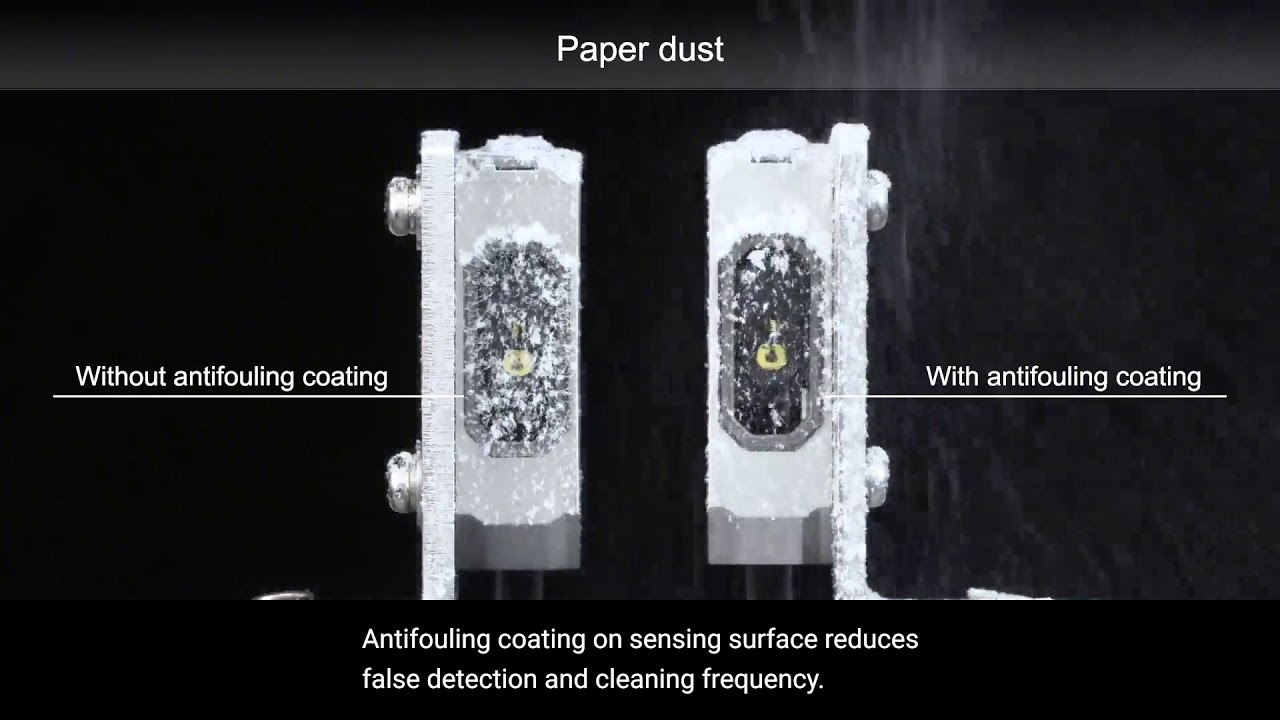

Easy to commissioning and maintenance for Food Industry with E3AS Sensors from OMRON
-

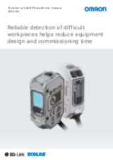
OMRON E3AS Photoelectric Sensors | Reliable detection of difficult workpieces
Curved, glossy and irregular surfaces can be detected with the E3AS photoelectric sensors.
02:17
OMRON E3AS Photoelectric Sensors | Reliable detection of difficult workpieces
Curved, glossy and irregular surfaces can be detected with the E3AS photoelectric sensors.
-

OMRON E3AS Photoelectric Sensors | Flexible design for Automotive Industry with no reflectors
E3AS Series changes the way of using reflective photoelectic sensors. Versatile installation allows flexible design. E3AS-HL CMOS with sensing distance up to 500mm, ideal for inclined and close mounting, for example in automotive manufacturing applications.
02:39
OMRON E3AS Photoelectric Sensors | Flexible design for Automotive Industry with no reflectors
E3AS Series changes the way of using reflective photoelectic sensors. Versatile installation allows flexible design. E3AS-HL CMOS with sensing distance up to 500mm, ideal for inclined and close mounting, for example in automotive manufacturing applications.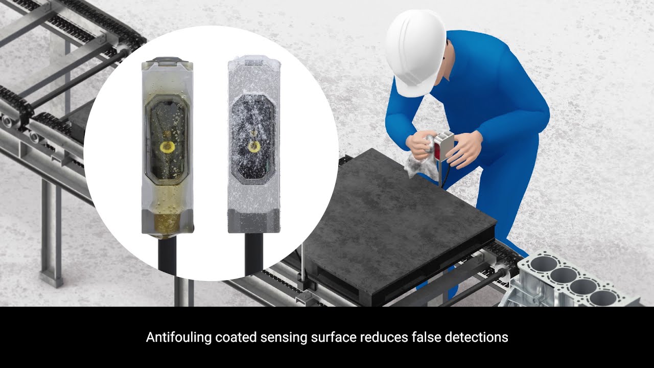
-

OMRON E3AS Photoelectric Sensors | Antifouling coated reduces false detection in Automotive Industry
Antifouling coating on sensing surface reduces false detection and cleaning frequency.
01:25
OMRON E3AS Photoelectric Sensors | Antifouling coated reduces false detection in Automotive Industry
Antifouling coating on sensing surface reduces false detection and cleaning frequency.

OMRON E3AS Photoelectric Sensors | Easy commissioning and maintenance for Automotive Industry

-

E3AS Photoelectric Sensors – Antifouling Lens Coating to prevent contamination sensing surface.
Antifouling Coating prevents contamination on the sensing surface and reduces false detection due to water droplets, oil, and dust. Dirty sensing surface of Photoelectric Sensors can cause false detection due to the principle of Photoelectric Sensors. Omron offers the industry’s first antifouling coating to prevent contamination on the sensing surface. The antifouling coating used on the E3AS series prevents contamination on the sensing surface in environments where oil or dust scatters, or steam generates. False detection and cleaning frequency are also reduced. Learn more at
01:28
E3AS Photoelectric Sensors – Antifouling Lens Coating to prevent contamination sensing surface.
Antifouling Coating prevents contamination on the sensing surface and reduces false detection due to water droplets, oil, and dust. Dirty sensing surface of Photoelectric Sensors can cause false detection due to the principle of Photoelectric Sensors. Omron offers the industry’s first antifouling coating to prevent contamination on the sensing surface. The antifouling coating used on the E3AS series prevents contamination on the sensing surface in environments where oil or dust scatters, or steam generates. False detection and cleaning frequency are also reduced. Learn more atVideo explicativo
-
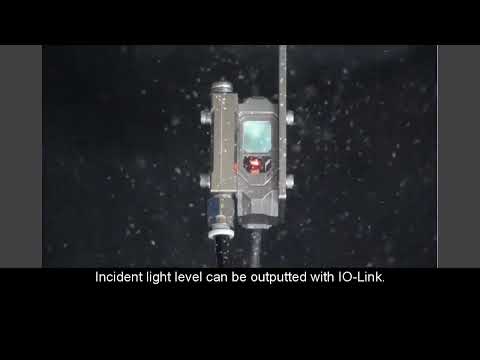
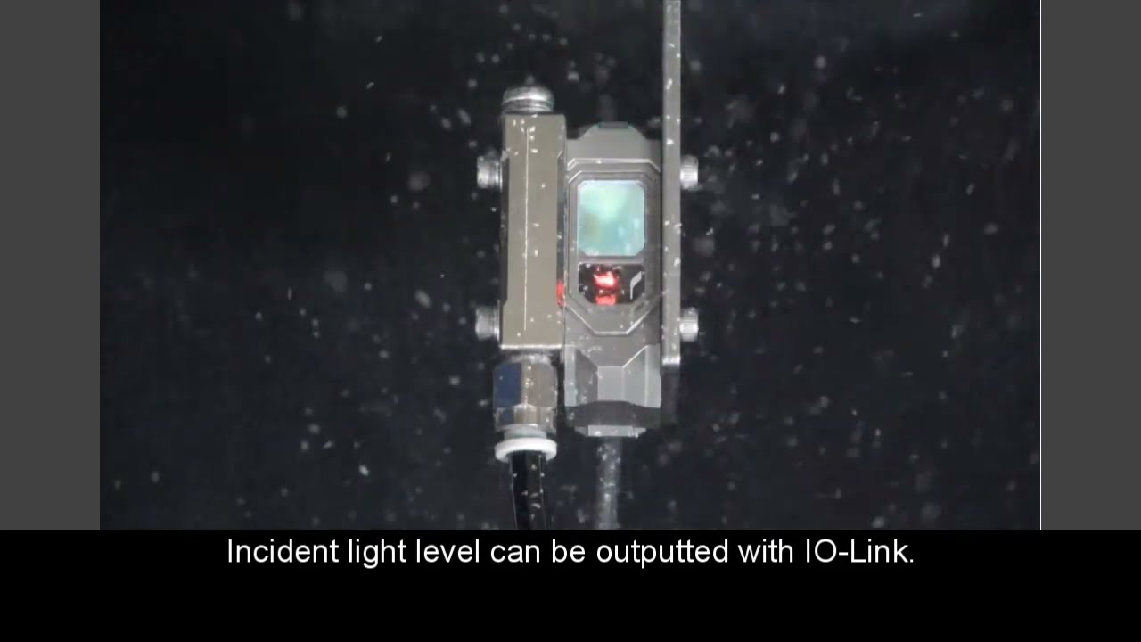
OMRON E3AS Predictive maintenance by using incident light level
Predictive maintenance example thanks to OMRON Air-blow accessory and IO-LINK #MakeitOMRON #industrialautomation
00:32
OMRON E3AS Predictive maintenance by using incident light level
Predictive maintenance example thanks to OMRON Air-blow accessory and IO-LINK #MakeitOMRON #industrialautomation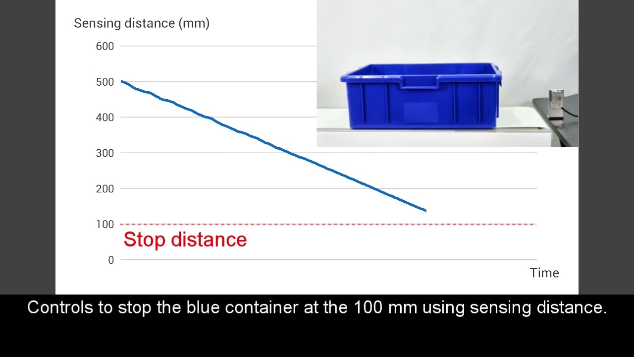
-

OMRON E3AS Control the stop position of workpiece by using detection value output
OMRON E3AS Position control through IO-LINK #MakeitOMRON #industrialautomation
00:45
OMRON E3AS Control the stop position of workpiece by using detection value output
OMRON E3AS Position control through IO-LINK #MakeitOMRON #industrialautomation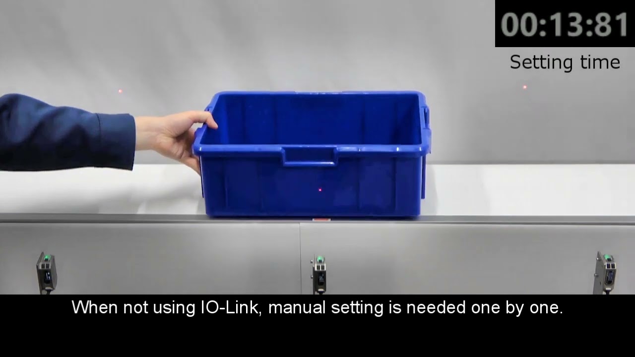
-

OMRON E3AS Shortening the setting time by setting the threshold value
OMRON E3AS fast commissioning through IO-LINK #MakeitOMRON #industrialautomation
01:04
OMRON E3AS Shortening the setting time by setting the threshold value
OMRON E3AS fast commissioning through IO-LINK #MakeitOMRON #industrialautomation

OMRON E3AS HL Pet Bottle Detection


OMRON E3AS F Colored Containers Detection

OMRON E3AS F Engine Block Detection


OMRON E3AS HL Bearing Detection

OMRON E3AS HL Can Detection

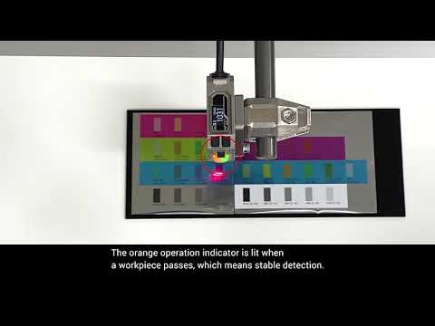
OMRON E3AS HL Colored Thin Workpieces Detection

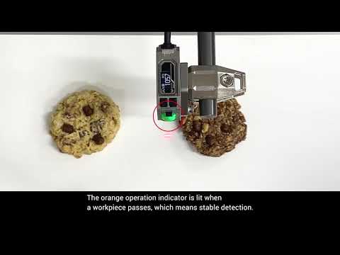
OMRON E3AS HL Cookies Detection

OMRON E3AS HL Glossy detection
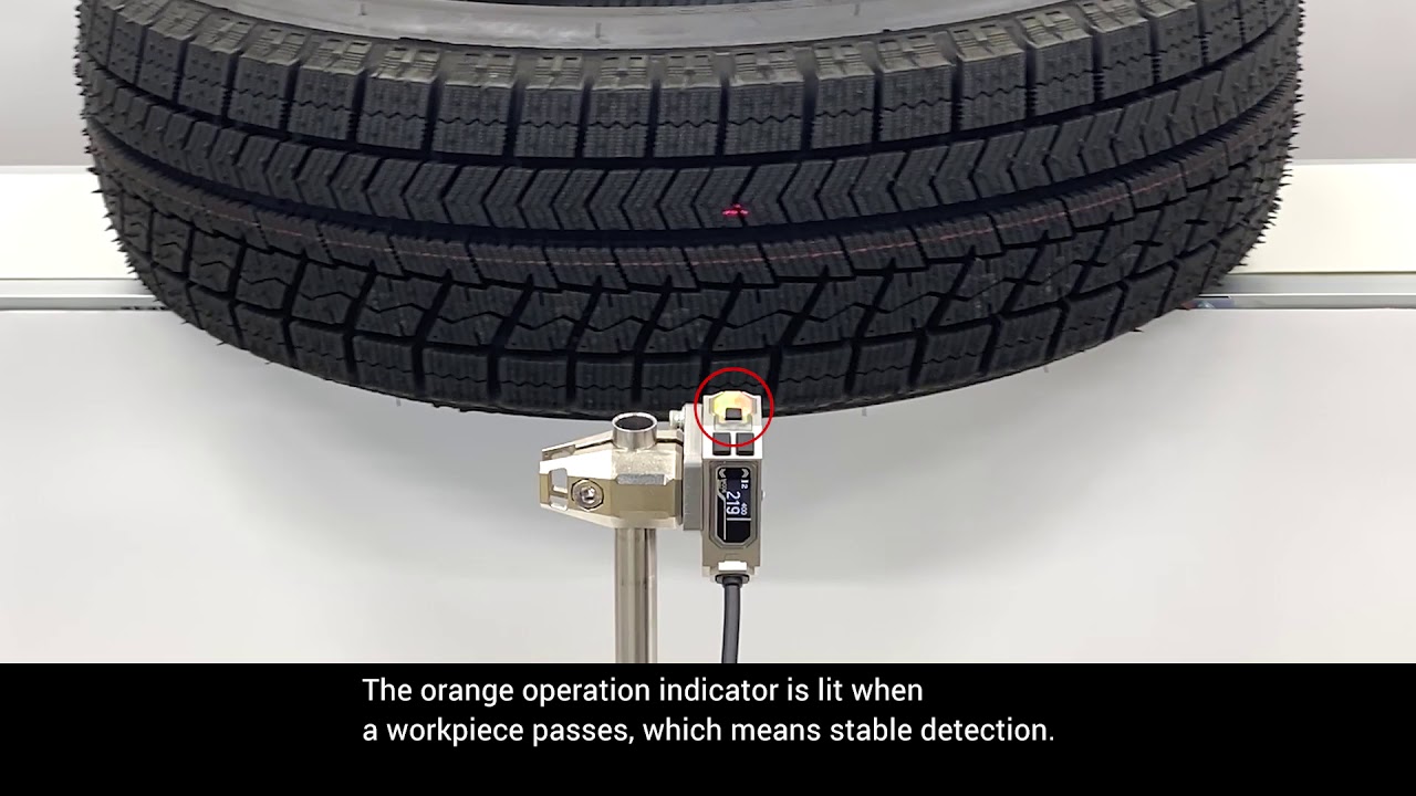

OMRON E3AS HL Tire Detection


OMRON E3AS L80 Cardboard Sheets Detection
Productos relacionados:
-
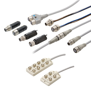
Juegos de cables y conectores industriales para cualquier aplicación
-
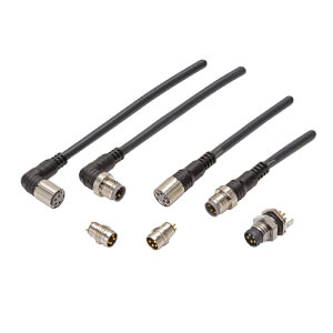
Juegos de cables y conectores industriales para cualquier aplicación
-
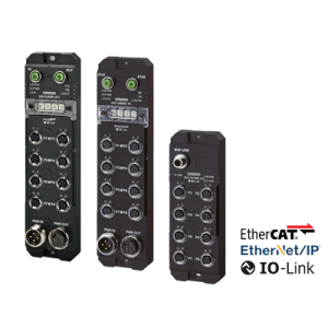
Entradas/salidas remotas IP67 sobre redes Ethercat y Ethernet/IP con funcionalidad de maestro IO-Link
Descargas