A2W
Pulsador inalámbrico
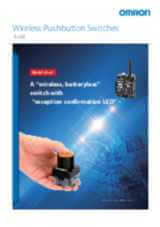
"Interruptor inalámbrico de banda sub-GHz que combina la fiabilidad inalámbrica con la facilidad de uso para mejorar los entornos de trabajo".
- La banda sub-GHz reduce las interferencias y mejora la propagación de la señal a las zonas de difícil acceso.
- La impedancia en la transmisión inalámbrica debida a daños o ruido se muestra mediante la salida de errores de la unidad maestra.
- El estado de recepción del botón esclavo se muestra mediante los LED de confirmación de recepción.
- La distancia de transmisión es independiente de la posición de transmisión del botón esclavo.
- La configuración se puede visualizar mediante herramientas de PC*, lo que evita el registro de identificaciones erróneas.
- La calidad de la señal se muestra en el display, y los entornos de uso se pueden ver mediante herramientas de PC*.
- 8 salidas con un enfoque de control descentralizado.
- La generación de alimentación automática elimina la necesidad de sustituir la batería y mejora la seguridad y el ahorro de energía en el botón esclavo.
- La forma del botón esclavo facilita su uso.
Especificaciones y modelos disponibles
| Producto | Application | Area | Bezel material | Color | Bezel color | Frequency | Profile | Reset method | Shape | Size | Suitable for illumination | Descripción | |
|---|---|---|---|---|---|---|---|---|---|---|---|---|---|
|
|
Wireless Pushbutton switch | Europe (EU) | Plastic | Blue | Black | 868.3 MHz | Mushroom | Momentary | Round | 40 mm | Yes | Wireless Mushroom button, dia. 40 mm, EU frequency 868.3 MHz, Button/flange colors blue-black |
|
|
|
Wireless Pushbutton switch | Europe (EU) | Plastic | Black | Black | 868.3 MHz | Mushroom | Momentary | Round | 40 mm | Yes | Wireless Mushroom button, dia. 40 mm, EU Frequency 868.3 MHz, Button/flange colors black-black |
|
|
|
Wireless Pushbutton switch | Europe (EU) | Plastic | Green | Black | 868.3 MHz | Mushroom | Momentary | Round | 40 mm | Yes | Botón de seta inalámbrico, diám. 40 mm, frecuencia UE 868,3 MHz, colores de botón/brida: verde y negro |
|
|
|
Wireless Pushbutton switch | Europe (EU) | Plastic | Red | Black | 868.3 MHz | Mushroom | Momentary | Round | 40 mm | Yes | Wireless Mushroom button, dia. 40 mm, EU frequency 868.3 MHz, Button/flange colors red-black |
|
|
|
Wireless Pushbutton switch | Europe (EU) | Plastic | White | Black | 868.3 MHz | Mushroom | Momentary | Round | 40 mm | Yes | Wireless Mushroom button, dia. 40 mm, EU frequency 868.3 MHz, Button/flange colors white-black |
|
|
|
Wireless Pushbutton switch | Europe (EU) | Plastic | Yellow | Black | 868.3 MHz | Mushroom | Momentary | Round | 40 mm | Yes | Wireless Mushroom button, dia. 40 mm, EU frequency 868.3 MHz, Button/flange colors yellow-black |
|
|
|
Wireless Pushbutton switch | Europe (EU) | Plastic | Blue | Black | 868.3 MHz | Full guard | Momentary | Round | 34 mm | Yes | Wireless Full guard button, dia. 34.4 mm, EU frequency 868.3 MHz, Button/flange colors blue-black |
|
|
|
Wireless Pushbutton switch | Europe (EU) | Plastic | Black | Black | 868.3 MHz | Full guard | Momentary | Round | 34 mm | Yes | Wireless Full guard button, dia. 34.4 mm, EU frequency 868.3 MHz, Button/flange colors black-black |
|
|
|
Wireless Pushbutton switch | Europe (EU) | Plastic | Green | Black | 868.3 MHz | Full guard | Momentary | Round | 34 mm | Yes | Wireless Full guard button, dia. 34.4 mm, EU frequency 868.3 MHz, Button/flange colors green-black |
|
|
|
Wireless Pushbutton switch | Europe (EU) | Plastic | Red | Black | 868.3 MHz | Full guard | Momentary | Round | 34 mm | Yes | Wireless Full guard button, dia. 34.4 mm, EU frequency 868.3 MHz, Button/flange colors red-black |
|
|
|
Wireless Pushbutton switch | Europe (EU) | Plastic | White | Black | 868.3 MHz | Full guard | Momentary | Round | 34 mm | Yes | Wireless Full guard button, dia. 34.4 mm, EU frequency 868.3 MHz, Button/flange colors white-black |
|
|
|
Wireless Pushbutton switch | Europe (EU) | Plastic | Yellow | Black | 868.3 MHz | Full guard | Momentary | Round | 34 mm | Yes | Wireless Full guard button, dia. 34.4 mm, EU frequency 868.3 MHz, Button/flange colors yellow-black |
|
¿Necesita ayuda?
Estamos aquí para ayudarle. Póngase en contacto con nosotros y nuestros especialistas le ayudarán a encontrar la mejor solución para su negocio.
Contacten conmigo A2W
Gracias por enviarnos su solicitud. Le responderemos lo antes posible.
Tenemos dificultades técnicas. Su formulario no ha sido enviado. Porfavor, acepte nuestras disculpas e inténtelo de nuevo más tarde.\ Detalle: [details]
DownloadPresupuesto para A2W
A través de este formulario puede solicitar cotización del producto escogido. Por favor, cumplimente todos los campos marcados con *. Sus datos personales serán tratados con la máxima confidencialidad.
Gracias por la cotización solicitada. Le enviaremos la información solicitada lo antes posible.
Tenemos dificultades técnicas. Su formulario no ha sido enviado. Porfavor, acepte nuestras disculpas e inténtelo de nuevo más tarde.\ Detalle: [details]
DownloadVídeos
-

How to set up Omron A2W wireless pushbutton
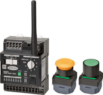
For more information: USA Canada Mexico Innovation created by a switch that connects people and machines wirelessly. A Wireless Call Button without a Battery. 8 pushbuttons can be assigned to one receiver unit. Each receiver has 8 transistor outputs (one-shot operation) A pushbutton can be assigned to multiple outputs of a receiver Self generated power created by the button operation eliminates the need for a power supply or batteries Wireless communication is confirmed with a colored LED indicator on the pushbuttons 922.5MHz frequency band reduces interference, providing a better signal in locations with obstacles A high-sensitivity magnetic-base antenna is an option when installing the receiver inside a control panel
03:34
How to set up Omron A2W wireless pushbutton
For more information: USA Canada Mexico Innovation created by a switch that connects people and machines wirelessly. A Wireless Call Button without a Battery. 8 pushbuttons can be assigned to one receiver unit. Each receiver has 8 transistor outputs (one-shot operation) A pushbutton can be assigned to multiple outputs of a receiver Self generated power created by the button operation eliminates the need for a power supply or batteries Wireless communication is confirmed with a colored LED indicator on the pushbuttons 922.5MHz frequency band reduces interference, providing a better signal in locations with obstacles A high-sensitivity magnetic-base antenna is an option when installing the receiver inside a control panel
-

Component Focus: Omron Wireless Buttons
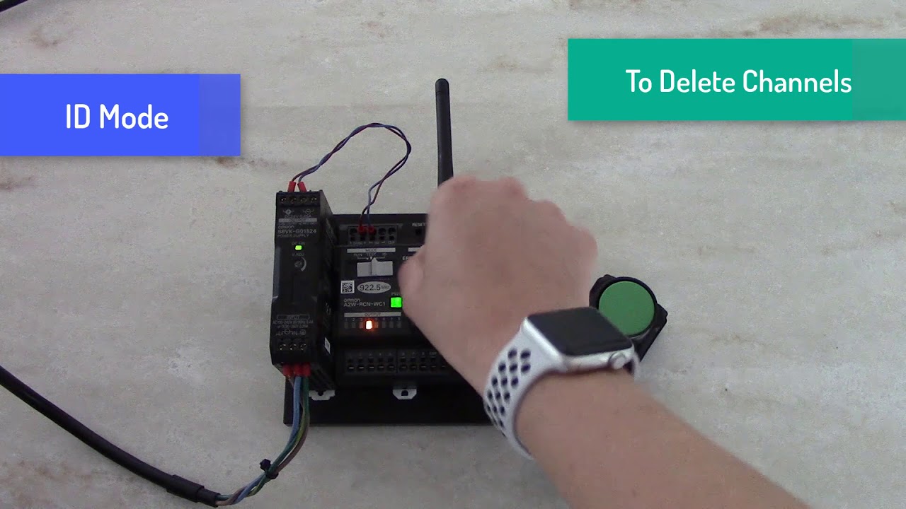
I'm Josh Bishop for cooling. It takes a wide voltage input from 100 to 240 volts AC and accepts either 50 or 60 Hertz. You can connect the incoming power here at the bottom with line, neutral and ground inputs. This particular power supply outputs the 24 volt DC power at the top with these terminal blocks and can provide up to 15 watts which is ample power for this wireless receiver or many other devices. There are other S8V caged power supplies that can output more power, but this works great in this case. The S8VK is providing power to this wireless receiver the A2W-RPC- WC1. This receiver is very straightforward to use with clearly marked ports and switches and common sense usage. This has eight outputs and accordingly can be synced with eight wireless buttons. You can see the power input up at the top and the outputs here at the bottom. There are lights for power, any potential errors and receipt of signals right here. There's also a slide switch for usage testing and setup. You'll note that this is 922.5 megahertz which gives it a greater range and better signal propagation than higher frequency signals. We end up with the communication assistance of about 100 meters without any obstructions. Finally we have the two push-button switches. They're obviously both wireless and they generate their own power so no battery is required. This also eliminates the need for maintenance. A light comes on when you click the button showing that it has been actuated and is working. They come with the space to allow you to easily mount them and swap them around as you need. The buttons are functionally the same, but you have the option of different types of plungers depending on what works best in your situation. They're both ULl certified, rated up to 1 million operations and are IP65 sealed. They're also shock and vibration resistant making them ideal for tough industrial application. All of this is connected and powered up. It is not set up and I'll walk you through the process just to show you how easy it is for you. You'll need to connect the S8VK to power. Again it can use power from practically anywhere in the world. Then hook the output of the power supply to the input of the wireless receiver and now everything will turn on and you'll be up to the point where I am currently. Programming the buttons and the receiver doesn't require anything external like a computer, you simply set the rotary switch to the channel you want to use, move the slide switch to ID and then click the button you want to use, 3 times relatively quickly. You'll see the receive light come on indicating that the receiver got the message and it has been paired. Switch to another channel do the same thing with the other button. That's it! It's recommended to make certain other systems in the area are not in use during this procedure, however, as it may cause problems. Let's move the slider switch to run and start clicking these buttons and watch those different indicators light up. Now deleting the buttons and reassigning them is just as easy; put the rotary switched to delete and click the button three times until the light comes on. The button is now unassigned and can be programmed to another output slot. With just a few components in a couple minutes of setup you can easily integrate Omron's wireless buttons into your systems. if you want to learn more or purchase these Omron components go to Features: - 8 pushbuttons can be assigned to one receiver unit - Each receiver has 8 transistor outputs (one-shot operation) - A pushbutton can be assigned to multiple outputs of a receiver - Wireless communication is confirmed with a colored LED indicator on the pushbuttons - 922.5MHz frequency band reduces interference, providing a better signal in locations with obstacles - A high-sensitivity magnetic-base antenna is an option when installing the receiver inside a control panel
04:08
Component Focus: Omron Wireless Buttons
I'm Josh Bishop for cooling. It takes a wide voltage input from 100 to 240 volts AC and accepts either 50 or 60 Hertz. You can connect the incoming power here at the bottom with line, neutral and ground inputs. This particular power supply outputs the 24 volt DC power at the top with these terminal blocks and can provide up to 15 watts which is ample power for this wireless receiver or many other devices. There are other S8V caged power supplies that can output more power, but this works great in this case. The S8VK is providing power to this wireless receiver the A2W-RPC- WC1. This receiver is very straightforward to use with clearly marked ports and switches and common sense usage. This has eight outputs and accordingly can be synced with eight wireless buttons. You can see the power input up at the top and the outputs here at the bottom. There are lights for power, any potential errors and receipt of signals right here. There's also a slide switch for usage testing and setup. You'll note that this is 922.5 megahertz which gives it a greater range and better signal propagation than higher frequency signals. We end up with the communication assistance of about 100 meters without any obstructions. Finally we have the two push-button switches. They're obviously both wireless and they generate their own power so no battery is required. This also eliminates the need for maintenance. A light comes on when you click the button showing that it has been actuated and is working. They come with the space to allow you to easily mount them and swap them around as you need. The buttons are functionally the same, but you have the option of different types of plungers depending on what works best in your situation. They're both ULl certified, rated up to 1 million operations and are IP65 sealed. They're also shock and vibration resistant making them ideal for tough industrial application. All of this is connected and powered up. It is not set up and I'll walk you through the process just to show you how easy it is for you. You'll need to connect the S8VK to power. Again it can use power from practically anywhere in the world. Then hook the output of the power supply to the input of the wireless receiver and now everything will turn on and you'll be up to the point where I am currently. Programming the buttons and the receiver doesn't require anything external like a computer, you simply set the rotary switch to the channel you want to use, move the slide switch to ID and then click the button you want to use, 3 times relatively quickly. You'll see the receive light come on indicating that the receiver got the message and it has been paired. Switch to another channel do the same thing with the other button. That's it! It's recommended to make certain other systems in the area are not in use during this procedure, however, as it may cause problems. Let's move the slider switch to run and start clicking these buttons and watch those different indicators light up. Now deleting the buttons and reassigning them is just as easy; put the rotary switched to delete and click the button three times until the light comes on. The button is now unassigned and can be programmed to another output slot. With just a few components in a couple minutes of setup you can easily integrate Omron's wireless buttons into your systems. if you want to learn more or purchase these Omron components go to Features: - 8 pushbuttons can be assigned to one receiver unit - Each receiver has 8 transistor outputs (one-shot operation) - A pushbutton can be assigned to multiple outputs of a receiver - Wireless communication is confirmed with a colored LED indicator on the pushbuttons - 922.5MHz frequency band reduces interference, providing a better signal in locations with obstacles - A high-sensitivity magnetic-base antenna is an option when installing the receiver inside a control panelDescargas