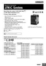
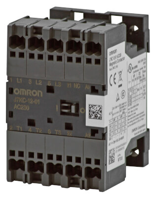
J7KC
Contactor magnético
La mejor opción para interruptores de motor y de lado primario para un máximo de 2,2 kW (240 V CA) *2, 5,5 kW (440 V CA)
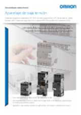
- La tecnología de cableado Push-In Plus permite ahorrar tiempo en el cableado y en el mantenimiento
- El más pequeño del mundo *1
- Ideal para el control de motores de hasta 2,2 kW (200 a 240 V CA)*2, 5,5 kW (380 a 440 V CA), categoría AC-3
- Alta fiabilidad de contacto (mín. 5 V CC, 3 mA)
- Unidad de atenuador de sobretensiones de la bobina instalada de serie*3
- Homologado de acuerdo con las principales normas de seguridad
*1. Según el estudio de OMRON a fecha de agosto de 2019.Para modelos Push-In.
*2. Basado en JIS C 8201-4-1
*3. Funcionamiento con CC
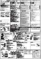
Especificaciones y modelos disponibles
| Producto | Main Contacts NO | Auxiliary Contacts NC | Operation voltage | Coil voltage | Rated power AC2, AC3 at 400 V [kW] | Rated current AC3 at 400 V [A] | Rated current AC1 at 690 V [A] | Rated current AC1 at 440 V [A] | Terminal type | Product Width (unpacked) | Product Height (unpacked) | Product Depth (unpacked) | Descripción | |
|---|---|---|---|---|---|---|---|---|---|---|---|---|---|---|
|
|
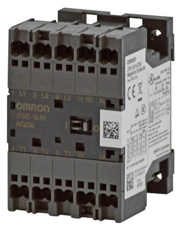
3 | 1 | DC | 24 V | 5.5 kW | 12 A | 5 A | 15 A | Push-in | 45 mm | 67.5 mm | 46 mm | Contactor para motores, 3 polos, terminales Push-In Plus, hasta 5,5 kW, 24 V CC, contactos: NA 3 NC 0, al. x an. x prof. 67,5 x 45 x 46 mm |
|
¿Necesita ayuda?
Estamos aquí para ayudarle. Póngase en contacto con nosotros y nuestros especialistas le ayudarán a encontrar la mejor solución para su negocio.
Contacten conmigo J7KC
Gracias por enviarnos su solicitud. Le responderemos lo antes posible.
Tenemos dificultades técnicas. Su formulario no ha sido enviado. Porfavor, acepte nuestras disculpas e inténtelo de nuevo más tarde.\ Detalle: [details]
Presupuesto para J7KC
A través de este formulario puede solicitar cotización del producto escogido. Por favor, cumplimente todos los campos marcados con *. Sus datos personales serán tratados con la máxima confidencialidad.
Gracias por la cotización solicitada. Le enviaremos la información solicitada lo antes posible.
Tenemos dificultades técnicas. Su formulario no ha sido enviado. Porfavor, acepte nuestras disculpas e inténtelo de nuevo más tarde.\ Detalle: [details]
Descargas