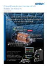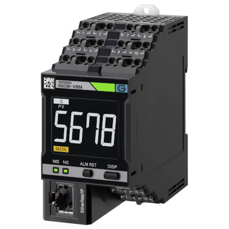
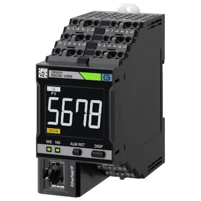
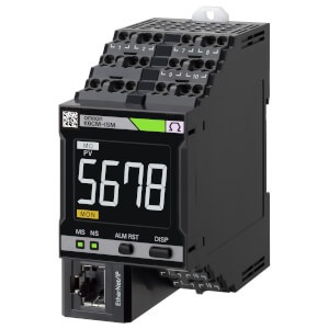
K6CM-VBM
Dispositivo de monitorización del estado del motor: monitorización de las vibraciones
El controlador K6CM-VBM analiza las vibraciones detectadas en los motores eléctricos para monitorizar el estado de la línea de transmisión del motor en su totalidad, sugiriendo que se realice el mantenimiento antes de que se produzcan problemas graves y, por lo tanto, evitando intervenciones imprevistas y costosos tiempos de inactividad.
Esta tecnología permite:
- Ser muy eficaz a la hora de detectar daños relacionados con los rodamientos del motor, gracias al análisis del tiempo y la frecuencia.
- Realizar la configuración de forma sencilla tanto en máquinas nuevas como en aquellas existentes, ya que la parametrización se realiza a través de una interfaz de software fácil de usar, que permite configurar el dispositivo en un par de minutos.
- Ser capaz de detectar anomalías, como un desequilibrio de la carga, correas mal alineadas o problemas del rotor y del estator.
- Notificaciones en caso de advertencia/alarma
- Monitorización remota
- Interacción con aplicaciones personalizadas y el servidor MQTT
Especificaciones y modelos disponibles
| Producto | Supply voltage AC | Supply voltage DC | Descripción | |
|---|---|---|---|---|
|
|
100-240 V | Monitorización de estado del motor, CA, trifásico, motor de inducción, modelo de análisis de corriente, 100 Vca/Vcc, salida de control a transistor, Push-in Plus, pantalla LCD, Ethernet IP |
|
|
|
|
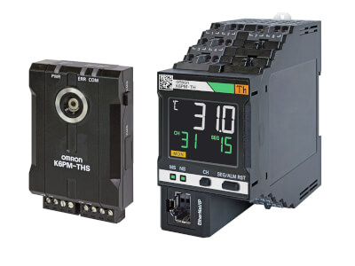
20.4-26.4 V | 20.4-26.4 V | Monitorización de estado del motor, CA, trifásico, motor de inducción, modelo de análisis de corriente, 24 Vca/Vcc, salida de control a transistor, Push-in Plus, pantalla LCD, Ethernet IP |
|
¿Necesita ayuda?
Estamos aquí para ayudarle. Póngase en contacto con nosotros y nuestros especialistas le ayudarán a encontrar la mejor solución para su negocio.
Contacten conmigo K6CM-VBM
Gracias por enviarnos su solicitud. Le responderemos lo antes posible.
Tenemos dificultades técnicas. Su formulario no ha sido enviado. Porfavor, acepte nuestras disculpas e inténtelo de nuevo más tarde.\ Detalle: [details]
Presupuesto para K6CM-VBM
A través de este formulario puede solicitar cotización del producto escogido. Por favor, cumplimente todos los campos marcados con *. Sus datos personales serán tratados con la máxima confidencialidad.
Gracias por la cotización solicitada. Le enviaremos la información solicitada lo antes posible.
Tenemos dificultades técnicas. Su formulario no ha sido enviado. Porfavor, acepte nuestras disculpas e inténtelo de nuevo más tarde.\ Detalle: [details]
Feature
El K6CM-VBM, especialmente adecuado para detectar anomalías relacionadas con los rodamientos, monitoriza los cambios en la velocidad de vibración y las aceleraciones y avisa con antelación, antes de que se produzca un problema grave, lo que permite planificar correctamente las intervenciones de mantenimiento.
Los dispositivos de monitorización de estado se pueden configurar con una sola herramienta
Configuración sencilla en tres pasos. La herramienta de configuración de monitorización de estado permite la configuración por lotes de una amplia gama de dispositivos de monitorización de estado, como los de motores, temperatura, aislamiento y calentadores. No requiere conocimientos especiales, lo que reduce el esfuerzo de formación.
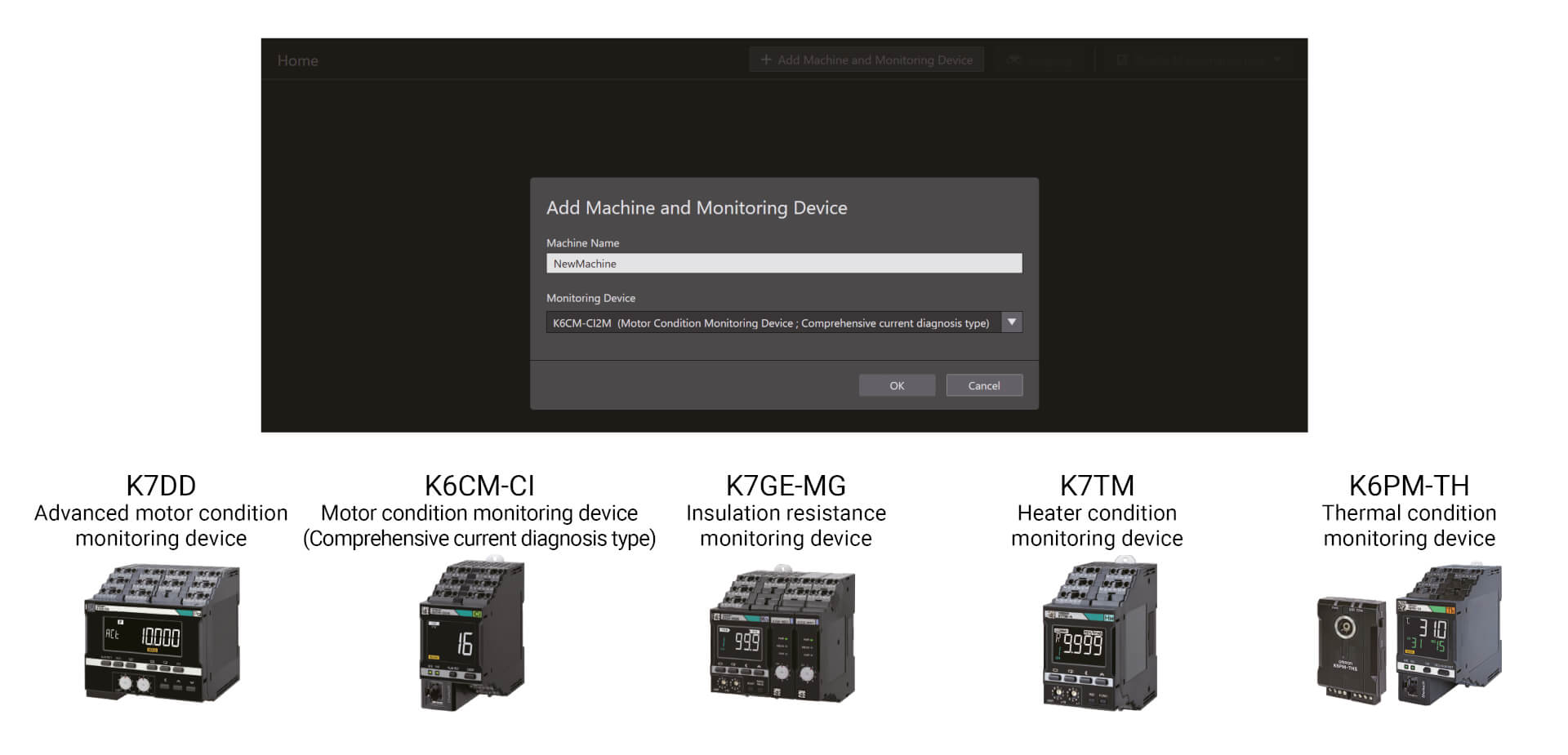
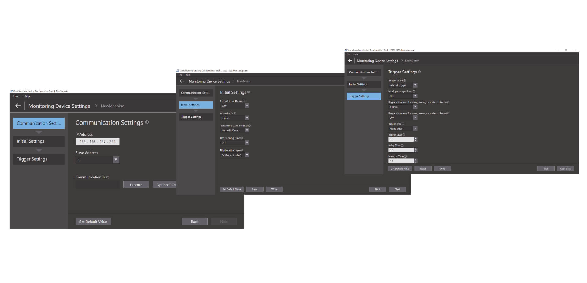
Configuración sencilla en tres pasos
La herramienta de configuración de monitorización de estado permite la configuración por lotes de una amplia gama de dispositivos de monitorización de estado, como los de motores, temperatura, aislamiento y calentadores. No requiere conocimientos especiales, lo que reduce el esfuerzo de formación. La configuración se puede completar en solo tres pasos: configuración de las comunicaciones, configuración inicial y configuración del activador.*1 Gracias a su gran facilidad de uso, la herramienta también aumenta la productividad in situ.
Vídeos

-
K6CM Motor Condition Monitoring Device
K6CM takes the burden of monitoring motors off maintenance engineers. Motors can be maintained in advance of failure due to deterioration. K6CM (comprehensive current diagnosis type) can consistently monitor motor conditions by observing the current waveform of the motor. Additionally, you can understand the motor's maintenance timing without depending on an engineer, because K6CM provides threshold value setting.
02:40
K6CM Motor Condition Monitoring Device
K6CM takes the burden of monitoring motors off maintenance engineers. Motors can be maintained in advance of failure due to deterioration. K6CM (comprehensive current diagnosis type) can consistently monitor motor conditions by observing the current waveform of the motor. Additionally, you can understand the motor's maintenance timing without depending on an engineer, because K6CM provides threshold value setting.
-

K6CM Demo Video
05:48
K6CM Demo Video
Soluciones
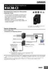
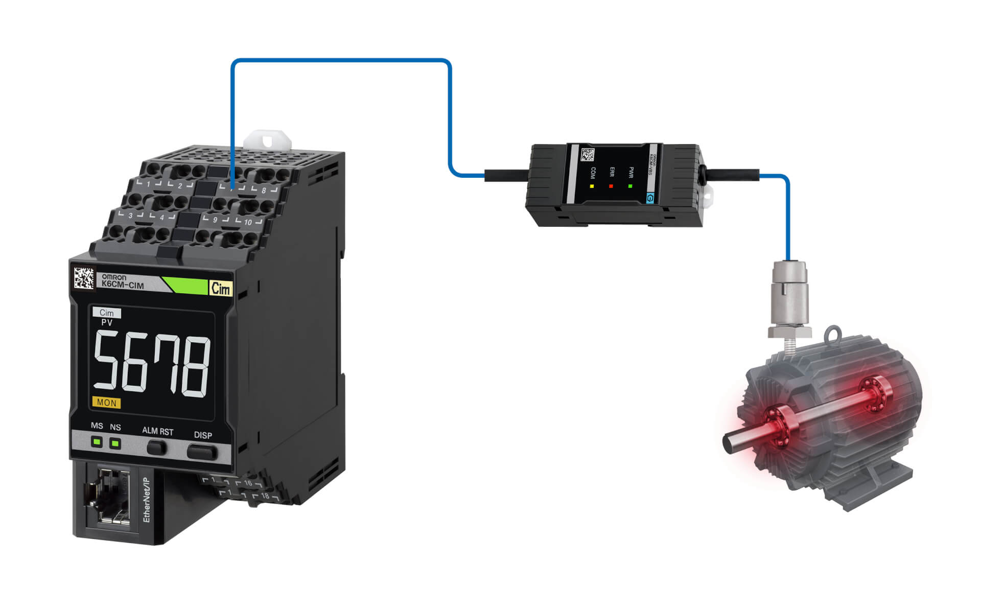
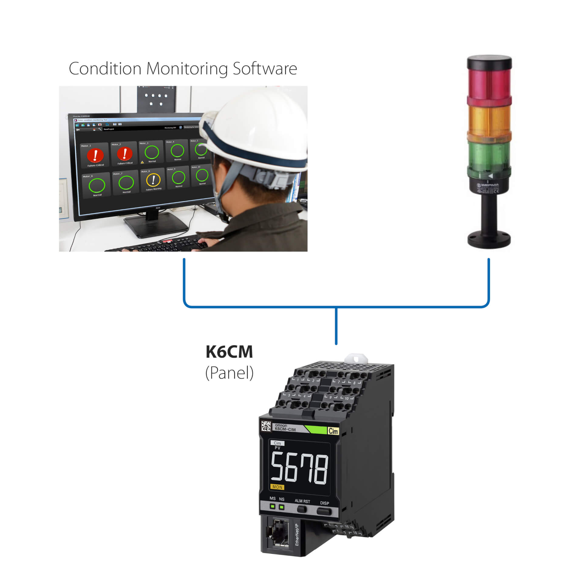
Instalación independiente (sin PLC)
Esta sencilla solución permite:
- Monitorizar el estado del motor a través del LED integrado o a través del software de monitorización del estado.
- Configurar los controladores mediante el software de monitorización del estado, suministrado con el dispositivo.
- Conectar el K6CM con cualquier dispositivo de E/S externo (como una salida digital).
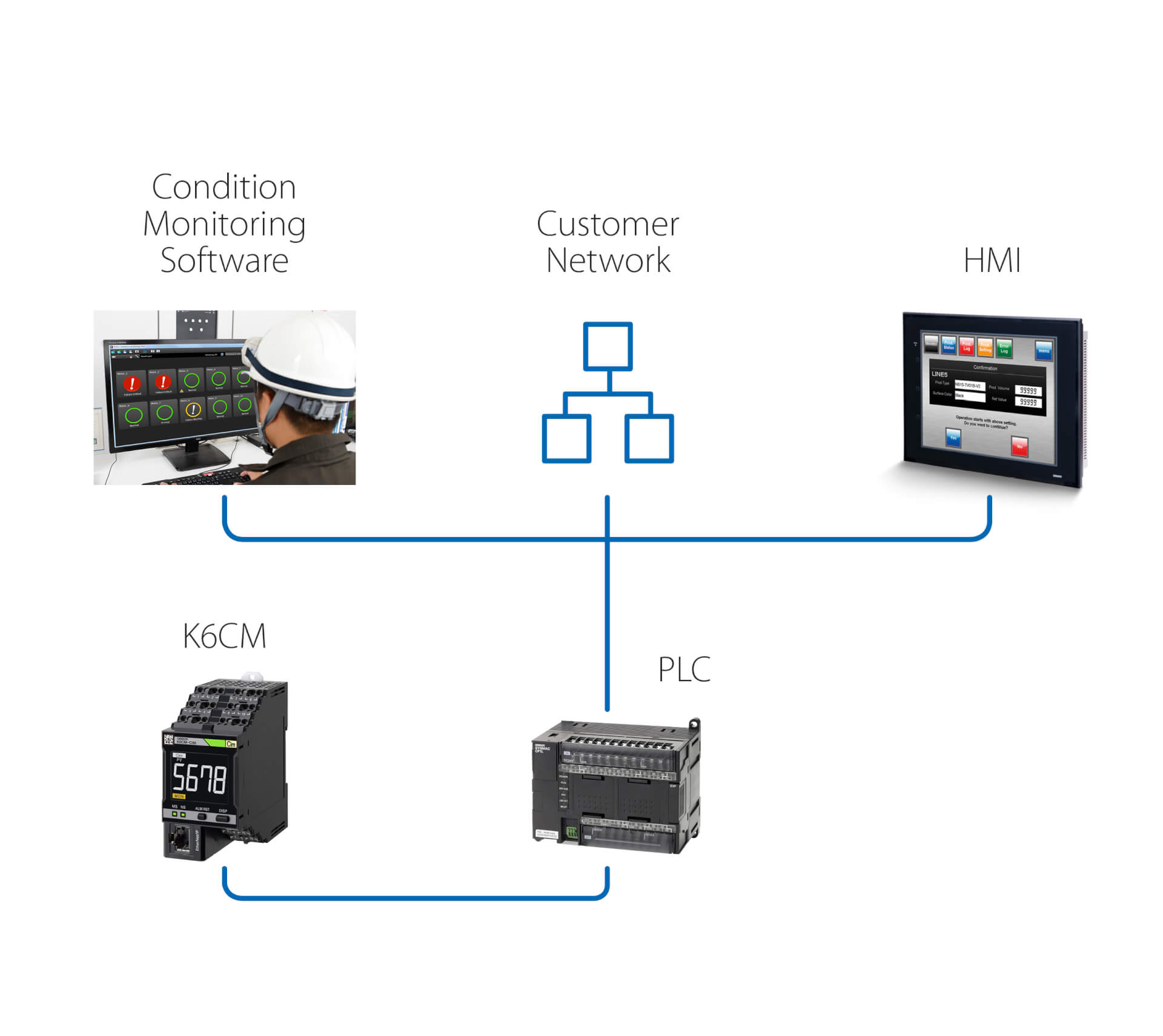
Instalación independiente (con PLC)
Esta solución permite, además de la solución anterior:
- Monitorizar el estado del motor a través del software de monitorización del estado, que se ejecuta en un PC conectado a través de un PLC.
- Activar, a través del PLC, acciones posteriores a cualquier advertencia/alarma detectada por el K6CM.
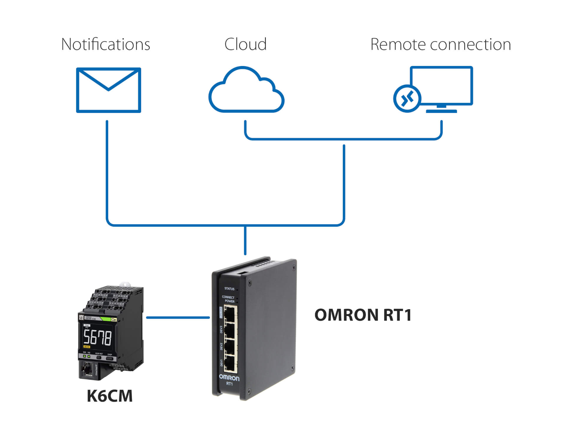
Notificaciones y monitorización remota, sin PLC
Esta solución, que utiliza la unidad OMRON RT1 como puerta de enlace, permite:
- Notificaciones por correo electrónico/SMS en caso de que el K6CM detecte anomalías.
- Una conexión segura (gestionada por la unidad RT1) a la nube, ya sea a través de LAN o a través de una conexión 4G.
- Una conexión segura para la configuración y la monitorización remotas del K6CM mediante el software de monitorización del estado suministrado con el controlador.
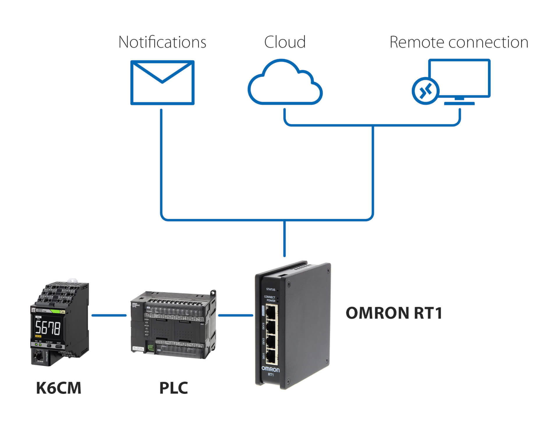
Notificaciones y monitorización remota, con PLC
Esta solución, que utiliza cualquier PLC y la unidad OMRON RT1 como gateway, permite:
- Notificaciones por correo electrónico/SMS en caso de que el K6CM detecte anomalías.
- Una conexión segura (gestionada por la unidad RT1) a la nube, ya sea a través de LAN o a través de una conexión 4G.
- Una conexión segura para la configuración y la monitorización remotas del K6CM mediante el software de monitorización del estado suministrado con el controlador.
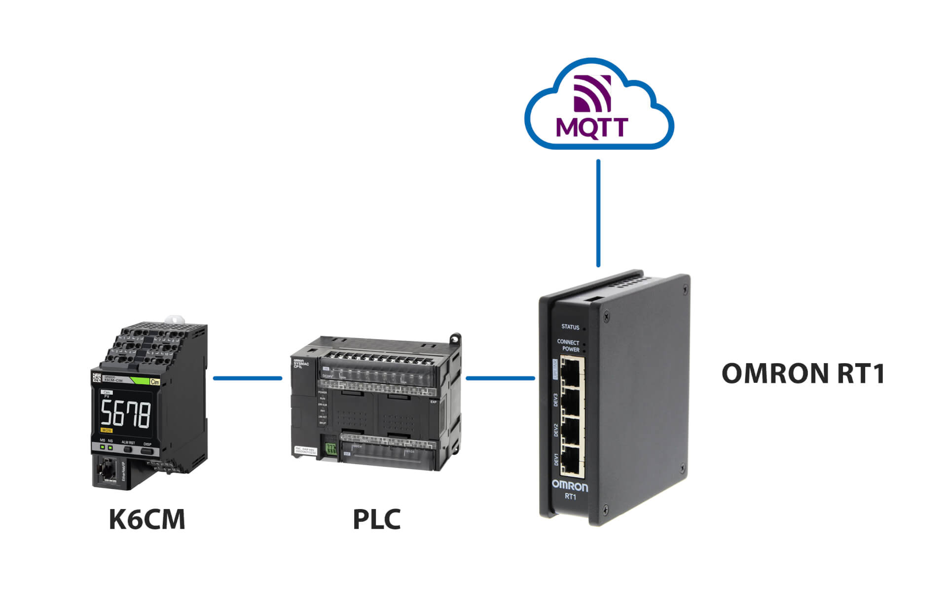
Conexión al servidor MQTT
Productos relacionados:
-
Dispositivo de monitorización del estado del motor: monitorización de la corriente
-
Dispositivo de monitorización del estado del motor: monitorización del aislamiento
-
Monitorización del estado basada en la termografía
-
Dispositivo de monitorización del estado: monitorización del aislamiento
Descargas